Flight Controls Abnormals
- James Albright (a former G450 driver)
Updated: 2018-02-02
The flight control system on the GV and G550 are about as close to perfection as is possible for the technology of the day.
The G450? Not so much. We have more than a few compromises but none worse than the mess caused by the so-called emergency flap system. The Hard Over Protection System (HOPS) is excellent and if you grew up in the older Gulfstreams you will be pleased by the pitch feel during flap movement.
Everything here is from the references shown below, with a few comments in an alternate color.
Elevator HOPS Activation
I've never heard of a hard over flight control malfunction in a Gulfstream but it is certainly possible. Should that happen, the Hard Over Protection System (HOPS) should remove hydraulic pressure from the offending actuator(s). The airplane is flyable without the hydraulics, but it is certainly not easy. The secret is to get the airplane into trim and fly it onto the runway by flaring without reducing the power until the wheels are the ground. If you pull the power, it will take both pilots with all the force they can muster to pull the elevator.
The HOPS is electrically powered to isolate the hydraulics, removing the electrons via the circuit breaker restores the hydraulics. Be very careful about turning a flyable airplane into an unflyable one.
More about this: Alaska Airlines 261.
People have died as a result of pilot induced oscillations at altitude, in a Falcon 900.
More about this: DA-900B SX-ECH.

Figure: G450 elevator HOPS switches, from G450 Maintenance Manual, §27-34-01, figure 503, sheet 3.
Symptoms
Unlike the other axis, the elevator HOPS can remove a single or both hydraulic systems. As a result, you may still have hydraulic pitch control and only be presented with the CAS message as an indication of elevator HOPS activation. If both left and right hydraulics are shut off to the elevator, however, you will only have manual reversion to control the elevator.
Elevator Hydraulics Off
Analysis
[G450 Airplane Flight Manual, §3-13-40] In the event an elevator actuator is out of phase with pilot input, the hydraulic system to that actuator will be shut off. Elevator HOPS activation is annunciated to the flight crew by an amber Elevator Hydraulics Off message displayed on CAS.
The elevator Hard Over Protection System (HOPS) has four switches that measure the elevator linkage movement for differences in mechanical and hydraulic movement of the linkage, and four switches internal to the actuator that measure pressures. If the switches detect a difference in input versus output for more than a tenth of a second, they electrically shut hydraulic pressure from the affected system. This shutoff is electric and can be reset or prevented by pulling the ELEV HYD S/O circuit breaker. Resetting the breaker restores protection, but it could also restore the problem that caused the HOPS activation in the first place.
Procedure
[G450 Airplane Flight Manual, §3-13-40]
IF ELEVATOR HOPS ACTIVATION HAS OCCURRED:
Autopilot . . . DISCONNECT
SPEEDBRAKES . . . RETRACT
CAUTION
WHEN THE ELEVATOR HYDRAULIC SHUTOFF CIRCUIT BREAKER IS PULLED, HYDRAULIC POWER FROM THE ASSOCIATED SYSTEM IS RESTORED TO THAT PORTION OF THE ACTUATOR. WHEN THE CIRCUIT BREAKER IS RESET, THE ACTUATOR WILL REMAIN POWERED IF NO HARDOVER IS DETECTED. IF A HARDOVER IS DETECTED, HOWEVER, THE SHUTOFF WILL BE REPEATED.
If the event started with a very large pitch change caused by an actual problem, pulling the circuit breaker will allow that same problem to recur.
IF CREW DETERMINES SHUTOFF IS FAULTY AND SYSTEM IS DEEMED NECESSARY FOR CONTINUED SAFE FLIGHT AND LANDING PERFORM STEP 3, OTHERWISE PROCEED TO STEP 4.
Example of a faulty shut off may be that you've just been upset by the wake of a passing heavy and got into a bit of a pilot induced pitch oscillation.
ELEV HYD S/O Circuit Breaker (POP, C-5) . . . PULL AND RESET ONCE
Take a firm grip of the yoke and be wary of making elevator reversals. A pilot induced oscillation could make the situation worse.
IF HOPS RESETS CONTINUE FLIGHT, OTHERWISE PROCEED TO STEP 4.
Landing Configuration . . . PLAN NORMAL FLAPS 39° LANDING
Airspeed . . . VREF FOR FLAPS 39°
NOTE:
With the loss of all hydraulic power to the elevator, high pitch control forces will result. Use of elevator trim is required for pitch control. During landing, use caution not to overuse trim for the landing flair, which can result in a ballooned landing. Consider using copilot to help with the flare if forces are high.
There are two techniques here:
If simulator experience is accurate, you can land this airplane without a flare at all if you are close to VREF. Whatever pull forces you can manage will certainly help.
You can also leave the power in, flare with less force required, and pull the power once both mains are on the ground.
Flaps Fail

We made a big deal of this in the GIII and GIV. Then, in the GV, we decreased our VREF by fifteen knots and it stopped being a big deal. Now, in the G450, we got ten of those knots back, but it still doesn't seem to be a big deal. I think it's because the brakes are so much better than they were with the GIV and we can now move the stabilizer to match the flaps.
You just need to line up the stab to match the flap with the PFD indication. Then return the EMER STAB switch to OFF and you can trim normally. A piece of cake.
CAS:
Flaps Failed
Symptoms:
Flaps have not achieved the flap handle commanded position
Analysis:
The flaps have not moved or have stopped short of the position commanded by the flap handle. This can be caused by mechanical interference, mechanical failure, or an electrical problem between the flap handle and the flap hydraulic motor. Of these problems, the only one you can work around is if the electrical problem lies in the FSECU. The procedure has you bypass the FSECU with the ALT FLAP switch. If that doesn't work, you are going to land with the flaps where they are.
Procedures:
[AFM, § 3-12-80]
If the flaps fail to extend when commanded, the primary channel of the FSECU may be the cause. Proceed as follows:
FLAP Handle ... RESELECT TO PREVIOUS POSITION
ALT FLAP Switch ... ARM
FLAP Handle ... SELECT FLAPS TO DESIRED POSITION
If flaps extend normally, proceed with normal landing. If flaps do not extend normally, see Partial or Jammed Flaps Landings
Emergency Stabilizer ... ARM
Horizontal Stabilizer ... MATCH TO FLAPS POSITION
NOTE: With stab armed, normal pitch trim is unavailable other than manual trim using the normal trim wheel. Electric pitch trim must be disengaged (DISENG) in order to use the trim wheel. Engaging the autopilot will allow the autopilot to trim the airplane using normal electric pitch trim.
If stabilizer matches flap position, proceed to Step 7.
If stabilizer fails to move:
Emergency Stabilizer ... OFF
VREF ... APPROPRIATE TO CONFIGURATION
GPWS / GND SPLR FLAP ORIDE ... ON / AS REQUIRED
Landing Gear ... DOWN / 3 GREEN
Ground Spoilers ... ARMED
Touchdown Ground Speed ... 195 KNOTS MAXIMUM
Flaps-Preflight
Moving the flaps for prefight . . . don't until you have AC power.
The Issue
Since you normally park the airplane with the flaps up to protect all the mechanisms forward of the flaps, you will need to extend the flaps for preflight. But in any GV series airplane, the flaps and stabilizer are connected electronically. The flaps require hydraulic pressure and DC electrical power. The stabilizer requires AC electrical power. If you move one without the other, computers become upset.
The preflight procedure to extend the flaps on battery power comes from the GV:

This works great in a GV so they put it in the G450, which has a flap system that is almost identical:

When we took delivery, this method worked about half the time. We complained that the system wasn't identical, the G450 has that pesky ALT FLAP switch. So the preflight procedure was changed to:

That never worked.
Solution
If you make the mistake of using any of these procedures in a G450 and end up with a "Flaps Fail" message and possibly a few others, you can try pulling and resetting the three flap control circuit breakers:
FLAP / STAB PRI L DC: POP, C-6
FLAP / STAB PRI R RC: CPOP, C-6
FLAP / STAB SEC DC: POP, E-1
That doesn't always work, sometimes you need to do a full power shutdown and restart.
Having learned your lesson, you should do what most G450 crews do: wait until you have AC power before moving the flaps.
Frozen Pitch Trim
The airplane is certainly flyable without pitch trim, so long as you still have control of the stabilizer. But if you lose pitch trim, there are steps you can take to get it back. It helps to understand how the elevator pitch trim system works and how each of several switches impacts operation of electric and manual pitch trim.
This checklist assumes the elevator pitch trim tabs are frozen, that is, iced over.
If you follow the procedure and still end up with frozen pitch trim, don't fret. The airplane is perfectly flyable using the stabilizer to trim pitch forces. I worry about trying to repeatedly free a stuck control surface, even a trim tab.
See: Alaska Airlines 261.

Figure: G450 elevator trim control rigging, from G450 Maintenance Manual, §27-33-00, figure 501, sheet 1.
Symptoms
[G450 Airplane Flight Manual §3-13-70] Inoperative pitch trim may be due to mechanical failure or binding of one or more system components from ice accumulation in the trim mechanism. The first indication of frozen pitch trim is an AP 1-2 Fail caution message on CAS caused by the inability of the autopilots to trim elevator control forces.

Photo: Pitch trim servo
Your normal pitch trim mode is through an electric trim servo that reacts to your inputs via the electric trim switches on each yoke, or from the autopilot. If the electric servo is unable to move the trim tab, you will probably get an AP 1-2 Fail CAS message. The problem could be one of these servos, in which case checking their circuit breakers would be in order. This procedure assumes you've already done this.
Each elevator trim tab is heated whenever the right main AC bus has power. You may need to cycle the power to these heaters or you may need to adjust altitude to find warmer air.
There is a lot of cable and are a lot of connection points between the manual trim wheel in the cockpit and the trim tabs on the elevator. (See the drawing at the top of this page.) A lot can conceivably go wrong, though this airplane does not have a track record of that. Fortunately, the GV series has an answer to the unlikely problem of frozen pitch trim. If all else fails, you can take control of the stabilizer away from the flap / stabilizer electronic control unit and trim pitch forces directly by moving the stabilizer by activating the EMER STAB switch.
Procedure
[G450 Airplane Flight Manual §3-13-70]
If either or both APs have hard failed because of frozen trim, check MAU #1A and MAU #2B circuit breakers listed below:
AP 1: MAU #1A PRI: POP, A-10, MAU #1A SEC: CPOP, A-10
AP 2: MAU #2B PRI: CPOP A-7, MAU #2B SEC: POP, A-7
IF FROZEN PITCH TRIM IS SUSPECTED:
A/P DISC (Either Control Wheel) . . . PRESS AND HOLD
A binding electric trim servo will stop the cables from moving and could be the source of trouble. Pressing the A/P DISC switch will remove electrical power to the servos as long as the switch is depressed.
Electric Pitch Trim . . . DISENG
The electric pitch trim switch removes power from the servos completely, however engaging the autopilot will attempt to reengage the servos.
A/P DISC . . . RELEASE
ELEV TRIM HEAT Circuit Breakers . . . CHECK IN, CYCLE IF NECESSARY
L ELEV TRIM HEAT: REER, E-16
R ELEV TRIM HEAT: REER, F-16
Ten (10) Minute Time Period . . . ALLOW TO ELAPSE
It might be a good idea to pull up the AC synoptic and watch the load on the right main AC bus. The problem could very well be a short in one of those heaters and you may not want to reset it. Remember, the airplane is flyable with frozen pitch trim.
Pitch Trim . . . ATTEMPT TO FREE USING MANUAL PITCH TRIM WHEEL
CAUTION DO NOT USE EXCESSIVE FORCE IN MOVING THE MANUAL PITCH TRIM WHEEL. THE PITCH TRIM SYSTEM HAS A SHEAR PIN INCORPORATED TO PROTECT THE SYSTEM FROM EXCESSIVE FORCES. IF THE PIN IS SHEARED, FUTURE USE OF PITCH TRIM WILL NOT BE POSSIBLE.
IF PITCH TRIM CANNOT BE FREED AND DESCENT TO WARMER ALTITUDE IS NOT FEASIBLE:
Airspeed . . . MAINTAIN CURRENT TRIMMED AIRSPEED FOR CRUISE FLIGHT
If climbs or descents are necessary, disconnect the autopilot and manually fly the airplane to new altitude. Determine trimmed airspeed for new altitude and adjust power as required. Engage autopilot if desired.
Descent To Warmer Altitude (If Possible) . . . COMPLETE BEFORE ATTEMPTING ANY FURTHER CONFIGURATION CHANGES WHEN BELOW 20,000 FEET MSL:
Keep in mind that a warmer altitude may actually be above you.
Pitch Trim . . . ATTEMPT TO FREE USING ELECTRIC PITCH TRIM SWITCHES
Attempt to free pitch trim by cycling electric pitch trim switches. If unable, select pitch trim OFF and re-attempt to free pitch trim using firm pressure on manual pitch trim wheel.
Certainly give this a try, but if it doesn't work remember the next step gives you a perfectly flyable airplane.
EMER STAB . . . ARM / USE AS NECESSARY TO TRIM CONTROL FORCES
CAUTION CARE SHOULD BE TAKEN WHEN CHANGING CONFIGURATION TO AVOID RAPID CONTROL FORCE BUILDUP.
FOR APPROACH AND LANDING WITH PITCH TRIM INOPERATIVE:
Flaps . . . POSITION NORMALLY AND USE EMER STAB TO TRIM CONTROL FORCES
Normal Landing . . . PERFORM
Jammed Ailerons
Find a long runway aligned with the wind and with an ILS. Fly the aircraft on the HUD keeping the FPV over the FD using the yoke for pitch only and the rudder for roll while ignoring the slip indicator. Keeping the bank under ten degrees and later to five degrees makes life easier -- just like flying a no-gyro PAR. The aircraft is landable.
There is help with the HUD:


Unlike the other aircraft in the GV series, you can't disconnect the ailerons in a G450.
CAS:
None.
Symptoms:
The ailerons will not move.
QRH:
None.
Analysis:
Unlike every other Gulfstream before it, the G450 has no way to isolate ailerons so once they are jammed, they are going to stay jammed. You can press the LATERAL CONTROL switch to remove all hydraulic pressure from the ailerons and spoilers to eliminate adverse spoiler effects. You will have to control the aircraft with the rudder.
Jammed Stabilizer
This shouldn't be a surprise if you remember to look at the flaps and stabilizer indicator every time you move the flaps. Once the jammed stabilizer is noted, simply moving the flaps back makes everything better. At that point, you are dealing with a landing with less than full flaps. (And you can do that.)
CAS:
You might get this:
Stabilizer Failed
In which case you would do the Stabilizer Failed checklist and if that didn't work, you would end up back here.
Symptoms:
The stabilizer doesn't move with the flaps.
Analysis:
The stabilizer moves in response to the flaps, as commanded by the FSECU. If the stabilizer doesn't move, you will be out of trim. Returning the flaps to match the stabilizer eliminates the trim problem.
Procedures:
[AFM, § 4-13-44]
On takeoff:
Airspeed ... MAINTAIN MINIMUM OF V2 +10 KTS AFTER LIFTOFF AND DURING CLIMBOUT
If Runway Length Is Not Available ... FLY FLAPS 20° APPROACH, USE FLAPS 39° FOR LANDING
Approach Speed ... DETERMINE
NOTE: Depending on weight and CG, VREF +10 kts approach speed may be necessary to alleviate elevator control forces which may result if attempting to fly VREF with pitch trim at the nose up limit.
In flight:
Further Flap Movement ... STOP
Airplane ... LAND AS SOON AS PRACTICABLE
NOTE: If further flight is necessary, match flaps to stabilizer position and observe appropriate placard speed.
If landing with stabilizer failed at 20° through 39° position, perform Step 6 and, if required, proceed to Step 9:
Flaps ... MATCH TO STABILIZER POSITION
NOTE: See Partial or Jammed Flaps Landings, if appropriate. If runway length is limited and the stabilizer is in the 20° position, then 39° flaps may be used for landing. In that condition, use full nose up elevator trim as required and expect heavy pull forces on final approach and during landing.
If landing with stabilizer failed at 0° through 19° position, perform Steps 7 and 8 and, if required, proceed to Step 9:
Flaps ... MATCH TO STABILIZER POSITION
NOTE: See Partial or Jammed Flaps Landings. If runway length is limited, 20° flaps may be used for landing. In that condition, use full nose up elevator trim as required and expect heavy pull forces on final approach and during landing.
GPWS/GND SPLR FLAP ORIDE ... ON FOR LANDING
If landing at a reduced flap setting is unavoidable, plan a wide approach and select the longest available runway. Once established:
VREF ... APPROPRIATE TO CONFIGURATION
NOTE: Plan a wide approach and observe VREF speed appropriate to configuration as shown in AFM Section 5: Approach and Landing, Normal Final Approach and Landing Performance Data Tables.
PWS/GND SPLR FLAP ORIDE ... ON / AS REQUIRED
NOTE: Landing with less than full flaps negates automatic ground spoiler deployment as result of wheel spin-up unless the GPWS/GND SPLR FLAP ORIDE is selected ON before landing. Ground spoiler deployment as result of weight-on-wheels should be normal.
Touchdown Ground Speed... 195 KNOTS MAXIMUM
CAUTION: TIRE SPEED LIMITATIONS WILL BE EXCEEDED IF TOUCHDOWN IS MADE IN EXCESS OF 195 KNOTS GROUND SPEED.
Partial or Jammed Flaps Landing
A no flap landing in the G450 is easier than the GIV but on paper it isn't. The G450 is approaches 5 knots slower but the AFM landing distance numbers are actually higher for a given set of conditions. No matter, it sure seems easier.
As soon as it is apparent you are landing without flaps, extend the gear. The added drag will make airspeed control easier.
The display controller will give you VREF based on the position of the flap handle. If the handle disagrees with the flaps, you can look it up in the pilot's checklist, last three pages.
Look for a runway with an electronic glide slope or an LPV, if not available look for a visual glide path source, and as a last choice set up a VPATH off the end of the runway.
Cross the threshold at VREF.
Pull throttles to idle at 100 feet.
Don't flare, just slight back pressure at 5 feet.

Procedure
[G450 AOM, #sect;3-12-30]
If landing at a reduced flap setting is unavoidable, fly a wide approach and select the longest available runway. Once established:
VREF ... APPROPRIATE TO CONFIGURATION
Plan a wide approach, and observe VREF speed appropriate as shown in AFM Section 5, Approach and Landing, Normal Final Approach and Landing Performance Data Tables.
GPWS/GND SPLR FLAP ORIDE ... ON
Select the ORIDE switch to ON if landing with flaps less than 22 degrees. This prevents the nuisance “TOO LOW FLAPS” aural alerts and provides backup capability to deploy the ground spoilers with wheel spin-up.
GND SPLR OFF / ARMED ... ARMED
Touchdown Ground Speed ... 195 KNOTS MAXIMUM
CAUTION: TIRE SPEED LIMITATIONS WILL BE EXCEEDED IF TOUCHDOWN IS MADE IN EXCESS OF 195 KNOTS GROUND SPEED
Landing Distance
[G450 AOM, #sect;06-05-60] If a full stop no flap landing is accomplished, it is recommended that a minimum runway length of 7,000 feet must be available.
The Performance Handbook has a good chart for landing distances. With PlaneBook, select the Performance Handbook and the "Landing Planning - PC" tab and it comes up on the very next page:
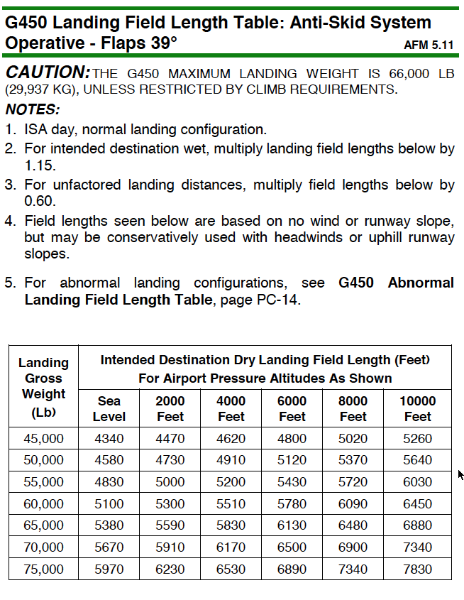
These distances are 0.60 factored, you should be able to stop in about 40% less runway.
At maximum landing weight near sea level, your factored distance should be about 5,500 feet, provided everything is working.
For abnormal conditions, like a partial flap landing, turn to page PC-14:

With 0° flaps, maximum weight, at sea level, that 5,500' distance climbs to 6,500' provide you still have anti-skid braking and the automatic ground spoilers are still working.
No Performance Handbook handy? The Pilot's Checklist (that spiral bound thing that gets lost in one of the side pockets) has all you need on page 25:

The bottom note tells you to multiply normal landing lengths by 26% to get no flap distances.
Lateral HOPS Activation
Flying the airplane with manual reversion can be a handful, it can be a bit sloppy. Landing with 20° flaps and an extra 10 knots should improve things a bit.
Symptoms
The ailerons cannot be "split" and losing hydraulics to the ailerons will also disable the flight spoilers.
Lateral Control Hyd Off
Analysis
The aileron HOPS uses force links connected to each actuator to sense a difference in the push or pull on an actuator versus what the actuator actually does. If the difference is too great for more than a half second, it electrically fires the lateral control shutoff switch to remove hydraulic pressure from the ailerons and spoiler system. This is done with a solenoid which requires electrical power to remain closed. Pulling the valve's circuit breaker opens it and resets the logic in the system. Closing the circuit breaker will allow the system to reclose if the condition causing it close in the first place still exists.
Procedure
[G450 Airplane Flight Manual, §3-13-30]
In the event either aileron actuator is out of phase with pilot input, both Left Hydraulic System (L SYS) and Right Hydraulic System (R SYS) power is removed from both ailerons and flight spoilers. Lateral HOPS activation is annunciated to the flight crew by an Amber Lateral Control Hyd Off message displayed on CAS.
IN THE EVENT OF AILERON HOPS ACTIVATION:
Autopilot . . . DISCONNECT
SPEED BRAKES . . . RETRACT
CAUTION
WHEN THE LATERAL HYDRAULIC SHUTOFF CIRCUIT BREAKER IS PULLED, HYDRAULIC POWER FROM THE ASSOCIATED SYSTEM IS RESTORED TO THAT PORTION OF THE AILERON AND SPOILER ACTUATORS. WHEN THE CIRCUIT BREAKER IS RESET, THE ACTUATORS WILL REMAIN POWERED IF NO HARDOVER IS DETECTED. IF A HARDOVER IS DETECTED, HOWEVER, THE SHUTOFF WILL BE REPEATED. IF CREW DETERMINES SHUTOFF IS FAULTY AND SYSTEM IS DEEMED NECESSARY FOR CONTINUED SAFE FLIGHT AND LANDING, PROCEED TO STEP 3, OTHERWISE PROCEED TO STEP 4.
LATERAL HYD S/O CB (POP, C-4) . . . PULL AND RESET ONCE
IF HOPS RESETS, CONTINUE FLIGHT. OTHERWISE, PROCEED TO STEP 4.
Airplane . . . PROCEED TO NEAREST SUITABLE AIRPORT AND LAND
NOTE:
If only lateral HOPS is activated, lateral control is degraded from normal and flight spoilers are not available.
Landing Configuration . . . PLAN FLAPS 20° LANDING
GPWS/GND SPLR FLAP ORIDE . . . ON
NOTE:
Ground spoilers will not be available on landing.
Airspeed . . . VREF FOR FLAPS 20° + 10 KTS
Mach Trim Failure
Gulfstream believes the G450 wing requires Mach trim above 0.75 MT, restricts your speed below this value if you don't have Mach trim, and will not allow you to dispatch without at least one Mach trim servo. We throw terms like "Mach tuck," "Mach trim," and "Mach number effect" and nod knowingly about the critical nature of it all. Yes, it is critical.
More about this: High Speed Flight.
So it is critical. But it is more critical in some airplanes than others. All Mach trim does for us, in the G450, is apply nose up elevator trim for us as we accelerate above 0.80 MT very smoothly and in small enough increments to make it all transparent to us when we hand fly the aircraft. It does this through the elevator electric trim servos using the autopilot computers. If the autopilot is engaged, the autopilot accomplishes Mach trim for us. If the autopilot is not engaged, the Mach trim function of the autopilot remains engaged and does it for us.
So how do you know if your undesired trim is being caused by a Mach trim failure? Read on . . .
Symptoms
[G450 Quick Reference Handbook, page MB-39]
CAS Message: Mach Trim 1-2 Fail
Cause(s): Both Mach trim channels have failed.
Corrective Action: Dispatch with reference to the MEL
[Gulfstream GV Series Master Minimum Equipment List, page 22-2, item 10.]
Item: Mach Trim Systems (GV-SP/GIV-X only)
Repair Category: C
Number Installed: 2
Number Required: 1
You should get a CAS message if the electrons have quit on you. If you don't get a CAS message and get uncommanded elevator trim inputs, it is probably the autopilot. If the autopilot isn't engaged, the Mach trim system can still make pitch trim inputs. If these inputs are not correct, you may have a Mach trim problem.
Analysis

Photo: Pitch trim servo, from Eddie's aircraft.
[G450 Aircraft Operating Manual §2B-08-100, ¶2.]
The Mach trim function is part of the autopilot and trims the aircraft nose-up for increasing Mach number and nose-down for decreasing Mach number during manual flight within the transonic flight region (0.85- 0.90 Mach for GV-SP, 0.80-0.93 Mach for GIV-X) by commanding elevator trim tab movement. The Mach trim function provides trim rate commands to the trim servo that drives the elevator trim tabs. The Mach trim control law with the addition of trim tab position feedback is used by the Mach trim function to control the aircraft. The rate command computed by the Mach trim function is based on air data Mach and elevator trim tab position information.
For GIV-X, the delta trim tab is applied as a function of delta Mach over the 0.80 to 0.93 transonic region is applied linearly to a maximum of 6.5°. For GV-SP, the delta trim tab is applied as a function of delta Mach over the 0.85 to 0.90 transonic region is applied linearly to a maximum of 1.7°.
Automatic activation of Mach trim should occur after any power-up within the Mach trim region or upon entry into the Mach trim region. The MT function deactivates if:
Mach number falls outside of the Mach trim range
AP is engaged
The manual trim switch inputs are on
AP quick disconnect inputs are on
MT switch is selected off
Trim tab servo is failed
Procedure
[G450 Airplane Flight Manual §3-02-40]
IF MACH TRIM FUNCTION RESULTS IN UNDESIRED PITCH TRIM, AND SELECTING THE OTHER FGC DOES NOT CORRECT THIS CONDITION, PROCEED AS FOLLOWS:
The QRH does not include the part of the note ". . . AND SELECTING THE OTHER FGC . . ." so if you are doing this procedure from the QRH and want to retain use of the autopilot, you should look at the AFM and give that other FGC a try.
A / P DISC (Either Control Wheel) . . . PUSH AND HOLD
Even if the autopilot isn't engaged, pushing and holding this button disengages Mach trim.
Electric Pitch Trim . . . DISENG
NOTE: Since electric pitch trim is no longer available, the manual trim wheel must be used.
A / P DISC . . . RELEASE
MMO . . . LIMIT TO 0.75 MT
Manual Reversion
There isn't much written on the subject of flying these Gulfstreams with all the hydraulics turned off. You practice it in the simulator which does a poor job of simulating the problem at hand. We used to practice these in the airplane from just after takeoff to just prior to the flare in the GIII and it was a workout. There isn't much by way of procedure but there are some useful techniques.
Analysis (Elevators)
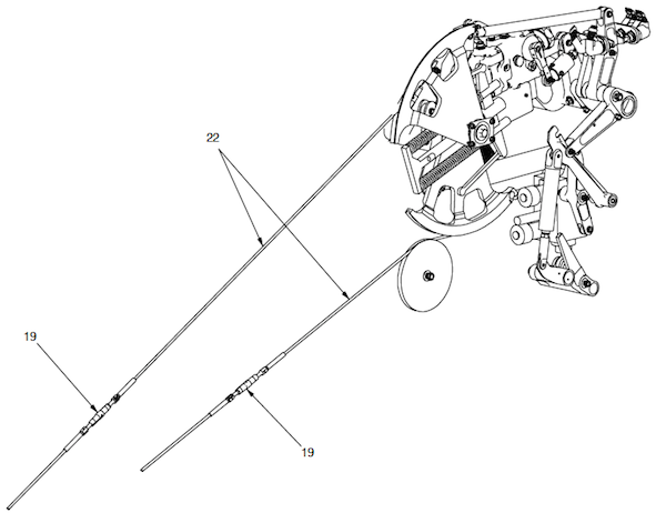
Figure: G450 Longitudinal control system, from G450 Maintenance Manual, §27-30-00, figure 503, sheet 7.
[G450 Maintenance Manual, §27-30-00, ¶4.A.]
Pilot/copilot inputs cause rotation of the cable sector which is pushrod connected to the actuator input crank. Both the actuator input crank and the output crank rotate on the same common pivot point and are linked together by a pin and elongated slot arrangement. The pin and slot arrangement permits differential motion between the two cranks until the pin bottoms at either end of the slot. The pin is attached to the actuator input crank and the elongated hole is on the output crank. The differential motion permits the input crank to move initially when an input is sensed, this motion is transmitted to the servo control valve input lever and causes the hydraulic actuator to stroke to the selected position. The actuator drives the output crank which transmits motion to the elevators through a series of connecting pushrods, idlers and cranks which are routed to the top of the vertical fin. Each elevator is driven separately by individual pushrods which link to a yoke-type crank at the top of the vertical fin.
Autopilot servo input to the longitudinal control system is through the cable sector. There is a separate set of cables leading from the longitudinal autopilot servo which are connected to separate sectors at this point. The autopilot servo inputs are introduced at the cable sector crank and displace the system to obtain the desired attitude about the pitch axis as called for by the autopilot.
Forward and aft movement of the control column moves the input crank (through the green pulley on the left) through a series of cables and pulleys. The input crank is has a pin that feeds into an elongated hole in the output crank (the pulley in the diagram above). Hydraulic servos react to the pin hitting either side of the elongated hole (see the brown lever in the diagram above) and attempt to center the pulley, providing hydraulic power to move the output crank, which is attached to the elevator through a series of pushrods and cranks. If hydraulic power is lost, the pin in the input crank moves the output crank directly.
With normal hydraulic pressure, the servo is working quickly to keep that pin centered so as soon as you make an input, the servo moves and the pin never really reaches either extreme. The result is almost a seamless translation for your pitch input to elevator response. Without hydraulic pressure pilot pitch inputs must move the actuator fully to move the pin to one extreme or another before any input is translated to the elevator. Not only will control pressures be higher, they will be delayed.
Analysis (Rudder)
[G450 Aircraft Operating Manual, §2A-27-30, ¶1] The rudder is positioned by inputs from the pilot or copilot rudder pedals, or by autopilot electro-servos. The pilot and copilot rudder pedals are connected by a common torque tube so that either may control rudder movement. The common torque tube is connected by a bell-crank to a single stranded wire cable loop located on the right side of the aircraft beneath the cockpit and cabin floor. The cable loop incorporates pulleys and bell-cranks to route the cable around other installations beneath the aircraft floor.
[G450 Maintenance Manual, §27-20-00 ¶2.D.] The right rudder cable connects to the upper part of the input sector while the left rudder cable connects to the lower side of the sector. Both the input sector and the output crank are joined at the center rear crank arm by a pin and slot arrangement. When the hydraulic actuator strokes, it drives the output crank which is a yoke-type arrangement rotating on the same axis as the sector assembly. There is a differential motion of ±4° between the sector and output crank due to the pin and slot arrangement (the slot is in the output crank and the pin is secured to the sector assembly). This differential motion is sufficient to create maximum valve displacement and to allow ±1-1/2° yaw damper authority from pilot selected position. In the event of complete hydraulic failure, the free motion of ±4° would exist between input and output until the pin bottoms in the slot to drive the output crank.
[G450 Aircraft Operating Manual, §2A-27-30 ¶1] The rudder actuator has a single shaft with a piston chamber for each (left and right) hydraulic system. Both hydraulic systems provide up to 3,000 psi pressure to assist in moving the rudder surface. Internal regulator valves limit the pressure output of the two pistons within the hydraulic actuator to a maximum of 1,500 psi. The output end of the hydraulic actuator shaft is connected to linkages that move the rudder around the pivot point connections on the vertical stabilizer. If one hydraulic system fails, the regulator valve of the remaining system shifts to provide up to three thousand (3,000) psi to move the rudder.
The rudder pedals are connected to the rudder actuator at a pin inside an elongated slot. The slot allows the actuator to apply hydraulic pressure in an attempt to keep the pin centered. If all hydraulic pressure is lost, rudder pedal movement is transmitted directly after the 4° of the slot is overcome. Rudder pressures will be increased and responsiveness will be delayed.
Analysis (Ailerons)
[G450 Maintenance Manual, §27-10-00 ¶2.] Both the pilot and copilot control wheels are mechanically connected. By displacing either of the control wheels, push-pull rods, bell cranks and 3/16 inch diameter cables are utilized to operate a control valve on the aileron servo actuator. The aileron actuator mechanical input system is tied in with the flight spoiler system. The aileron actuator is cradled in the power boost linkage between input crank and output crank with the lever ratios designed for a 6.5:1 boost ratio. For every unit of work done by the pilot, the actuator does four. Control valve displacement is caused by a relative rotation of input and output cranks about a common pivot. The valve is ported so that the output follows input with the motion of the actuator housing providing follow-up (feedback). Relative motion between input and output levers is limited by a pin in slot arrangement to the amount necessary to provide sufficient valve displacement to meet maximum piston velocity. The free play appears on manual reversion since valve error goes to 100% when there is no hydraulic power available. The actuator assembly contains an input damper which provides a force proportional approximately to the square of input velocity. The damper ensures stability in this type of power-boosted system which feeds a portion of the output load into the input system inertia. The aileron servo actuator is a tandem arrangement of two double-acting balanced cylinders supplied by separate hydraulic systems. If all hydraulics should fail or be shut off, the primary flight controls will revert to manual operation. The actuator contains cylinder bypass valves which open when system pressure drops below 60 psi. If both hydraulic systems fail or are shut off manually, the aileron actuator piston is free to idle as the pilot controls the ailerons manually.
The control wheels are connected to the ailerons with cables and can, if required, manually move the ailerons. The cables end in a pin located in a slot of each actuator. The actuator attempts to keep the pin centered using hydraulic pressure. Artificial feel is provided by hydraulic bungees that dampen motion. If the hydraulic pressure fails, the pin moves the entire actuator directly, albeit requiring more force and resulting in a little "slop" as the pin moves in the slot.
Procedure
[G450 Airplane Flight Manual, §05-15-10] In the event of a dual hydraulic failure, the airplane is controllable due to the manual reversion capability of the flight control system.
Techniques
Find a long, wide runway.
Fly a long final with plenty of course and glide path guidance, and ILS would be ideal.
Get on speed and once you've done that, keep the throttles constant. Dealing with thrust-induced pitch changes can become overwhelming closer to the ground.
Try to keep your lateral control inputs small to avoid any Dutch roll.
Fly the airplane onto the runway. The pull forces in the flare will be very high if you pull the power as usual. If you have the runway available, try leaving the power on until both mains are on the runway.
Rudder HOPS
The G450 rudder system is electronically monitored to ensure pilot inputs are precisely matched by rudder actuator outputs and if there is a problem, hydraulic pressure is removed. If the problem comes from only one hydraulic system, the remaining system is fully capable of operating on its own. If both systems are affected, you still have manual reversion of the rudder.
As with the other flight controls, if you believe the HOPS activation was a result of a momentary electrical issue, you can reset the system by pulling and resetting the circuit breaker. But, unlike the other flight controls, manual reversion of the rudder isn't really much of an ordeal. My take: when in doubt, leave the rudder hydraulic shut off circuit breakers alone.

Figure: G450 rudder HOPS block diagram, from G450 Aircraft Operating Manual, §2A-27-00, figure 11.
Symptoms
Rudder Hydraulics Off
(Either or both rudder HOPS activated.)
Single Rudder
(A single rudder HOPS activated.)
Analysis
[G450 Aircraft Operating Manual, §2A-27-30 ¶2.D.]
Movements of the rudder contrary to the commanded position are limited by a Hard Over Prevention System (HOPS) that incorporates eight switches to monitor mechanical and hydraulic rudder operation. If a malfunction occurs and the rudder moves opposite to or further from the commanded direction, the cam arm that is attached to the output linkage of the rudder actuator will move to close the clearance gap between the cam arm and the plunger-type switches, making contact with the switches on the side of the bracket. When the plungers of the switches are depressed, a relay closes and an electrical signal is sent to a corresponding set of switches mounted internally within the hydraulic actuator.
If both hydraulic systems are shut off, an amber caution message of "Rudder Hydraulics Off" is displayed. Manual rudder control may remain possible, depending upon the cause of the hard over condition. If the cause of the condition is thought to be momentary, and the use of the rudder is deemed necessary for continued safe flight and landing, the hydraulic shut off valves may be reset by cycling the RUDDER HYD S/O circuit breaker. If the cause has not been rectified, the shut off valves will close and hydraulic boost for the rudder will be unavailable. Loss of rudder hydraulic pressure will also prevent yaw damper (and autopilot rudder) operation.
If only one hydraulic system is shut off to the rudder, the remaining system will provide full boost to the rudder and yaw damper / autopilot rudder operation. The amber caution CAS message of "Rudder Hydraulics Off" will be accompanied by a blue advisory "Single Rudder" message.
The HOPS is triggered and actuated electrically. If electrical power is lost or the rudder hydraulic shut off circuit breaker is pulled, rudder hydraulic pressure will be restored.
Procedure
[G450 Airplane Flight Manual, §03-13-50]
In the event a rudder actuator is out of phase with pilot input, the hydraulic system pressure to that actuator will be shut off. Rudder HOPS activation is annunciated to the flight crew by an amber Rudder Hydraulics Off message displayed on CAS.
Autopilot . . . DISCONNECT
SPEEDBRAKES . . . RETRACT
CAUTION: WHEN THE RUDDER HYDRAULIC SHUTOFF CIRCUIT BREAKER IS PULLED, HYDRAULIC POWER FROM THE ASSOCIATED SYSTEM IS RESTORED TO THAT PORTION OF THE ACTUATOR. WHEN THE CIRCUIT BREAKER IS RESET, THE ACTUATOR WILL REMAIN POWERED IF NO HARDOVER IS DETECTED. IF A HARDOVER IS DETECTED, HOWEVER, THE SINGLE SYSTEM SHUTOFF WILL BE REPEATED.
IF CREW DETERMINES SHUTOFF IS FAULTY AND SYSTEM IS DEEMED NECESSARY FOR CONTINUED SAFE FLIGHT AND LANDING PERFORM STEP 3, OTHERWISE PROCEED TO STEP 4:
It is hard to imagine a case where you need rudder hydraulics for continued safe flight and landing. The rudder is the one axis of the flight controls which is easily controlled without hydraulics. Engine out your leg will be tired, no doubt about it, but the risk of a hard over rudder combined with an engine out can be catastrophic. Why risk it?
RUDDER HYD S/O Circuit Breaker (CPOP, C-3) . . . PULL AND RESET ONCE
Yaw Damper Inoperative Speeds . . . OBSERVE
Runway Selection . . . SELECT LONGEST AND WIDEST AVAILABLE WITH MINIMUM CROSSWIND COMPONENT
Landing Configuration . . . PLAN FLAPS 39° LANDING AT VREF
IF LANDING IN A CROSSWIND IS UNAVOIDABLE, USE ENGINE POWER TO COUNTER CROSSWIND EFFECTS. PLAN A LONG, SHALLOW APPROACH SETTING POWER AS REQUIRED TO ALIGN AIRPLANE WITH THE RUNWAY.
Nose Wheel Steering Pedals DISC . . . DISC
AFTER TOUCHDOWN:
Nose Wheel . . . LOWER TO GROUND IMMEDIATELY
Nose Wheel Steering . . . AS NECESSARY TO MAINTAIN RUNWAY CENTERLINE
Throttles . . . RETARD TO IDLE ONLY AFTER NOSE WHEEL STEERING IS ESTABLISHED
Runaway Pitch Trim
We used to worry about this a lot in some of the aircraft in my distant past. I've not heard of an issue in the Gulfstream but it is certainly possible. You could have a stuck electric switch in the cockpit or perhaps the servo goes nuts. If it happens, remember that red button on the yoke does more than just disconnect the autopilot and that you can maintain level flight with a lot of trim if you bank the aircraft. Runaway nose down pitch trim? There are a number of switches at your disposal and always remember the elevator is relatively small compared to the stabilizer, which you can control directly.
Symptoms
The pitch should react immediately to a runaway of the pitch trim so it should be obvious even without a CAS message.
Analysis
[G450 Aircraft Operating Manual §2A-27-20 ¶2.B.]
The elevator has two trim tabs installed on the trailing edge.
The trim tabs have a range of movement of 22° trailing edge down (aircraft nose up) to 8° trailing edge up (aircraft nose down). Limit switches are installed at the travel limits that will prompt the display of Crew Alerting System (CAS) messages notifying the crew that the elevator trim tabs are at maximum displacement.
The flight crew manually controls the amount of trim tab deflection by moving control wheels on either side of the center console. The wheels are hubs connected to a common axial shaft, so that moving one wheel moves the other. The shaft is connected to a continuous loop of wire cables that connect through a series of pulleys and bell-cranks to the elevator trim tabs.
This is written backwards. Manually controlling the trim tab is an emergency procedure. If you are used to fine tuning the manual pitch trim with other aircraft, don't do it with this one. You will be controlling the trim thusly...
The flight crew has the option of electrically moving the elevator trim tabs. A pushbutton, labeled PITCH TRIM ENG / DISENG, located to the left of the standby flight instruments on the lower instrument panel enables electrical operation of trim switches mounted on the outboard side of the control yokes.
The PITCH TRIM ENG / DISENG switch is automatically engaged whenever the autopilot is engaged (to enable autopilot trim). However the reverse is not true - electric pitch trim will not disengage when the autopilot is disengaged, but must be selected off with the switch.

The Nose Down/Nose Up switches on the control wheels are connected to the elevator trim tabs via an electric motor. The red disconnect switch depowers the electric trim servos for as long as the switch is depressed.

If you press the EMER STAB switch, the stabilizer is no longer connected to the computers and is now controlled by the NOSE Down/Nose Up switches you were using for the elevator trim.

The manual trim wheels directly move the elevator trim tabs but do not have the mechanical leverage to overcome the electric trim servos.

The electric trim servos can be disconnected using this switch.
Procedure
[G450 Airplane Flight Manual, §3-13-60]
IF RUNAWAY ELECTRIC PITCH TRIM IS DETECTED OR SUSPECTED:
A / P DISC (Either Control Wheel) . . . PRESS AND HOLD
PITCH TRIM ENG/DISENG . . . DISENG
The manual trim wheel will work now with the electric pitch trim servos disengaged.
CAUTION SUBSEQUENT ATTEMPTS TO ENGAGE THE AUTOPILOT WILL RESULT IN AUTOMATIC RE-ENGAGEMENT OF ELECTRIC PITCH TRIM.
You might consider pulling the electric pitch trim circuit breakers (ELEV SERVO #1 POP D-4 and ELEV SERVO #2 CPOP D-4) to avoid having to recover from runaway pitch trim a second time.
A / P DISC . . . RELEASE
ALTERNATE PROCEDURE:
Manual Pitch Trim Wheel . . . GRASP AND HOLD
PITCH TRIM ENG/DISENG . . . DISENG
CAUTION SUBSEQUENT CHANGES TO PITCH TRIM SHOULD BE MADE ONLY WITH THE MANUAL PITCH TRIM WHEEL.
Stabilizer Failed
If you end up with the stabilizer and flaps mismatched and selecting EMER STAB allowed you to fix everything, why not turn off the EMER STAB at that point so you will have normal trim?
CAS:
Stabilizer Failed
Symptoms:
The stabilizer doesn't move with the flaps.
Analysis:
The stabilizer moves in response to the flaps, as commanded by the FSECU. If the stabilizer doesn't move, you will be out of trim. Returning the flaps to match the stabilizer eliminates the trim problem. You can bypass the FSECU to move the stabilizer.
Procedures:
[AFM, § 3-12-90]
Note: If the Left Main AC Bus is not powered it will be necessary to select EMER STAB to operate the flaps and enable the pilot or copilot trim switches to reposition the STAB to match the FLAP position.
Airspeed ... REDUCE
Flap Handle .. .RETURN TO PREVIOUS POSITION
If stabilizer does NOT match flap position:
EMER STAB ... ARM
EMER STAB ... TRIM TO MATCH FLAP POSITION
If stabilizer does NOT move:
EMER STAB ... OFF
Proceed with partial flap landing:
VREF ... APPROPRIATE TO CONFIGURATION
GND SPLR FLAP ORIDE ... ON
Landing Gear ... DOWN / 3 GREEN
Ground Spoilers ... ARMED
If you have ever taken off in the simulator when the wizard behind the curtain hit the "Runaway Pitch Trim" lever in the nose down direction, you know you will have had your hands full. If the wizard throws the lever at too low an altitude, you will find yourself in simulator hell. The list of flight control abnormals for this airplane is fairly long. But it needs one more, as this letter illustrates.
.
Stabilizer Failed
If you end up with the stabilizer and flaps mismatched and selecting EMER STAB allowed you to fix everything, why not turn off the EMER STAB at that point so you will have normal trim?
CAS:
Stabilizer Failed
Symptoms:
The stabilizer doesn't move with the flaps.
Analysis:
The stabilizer moves in response to the flaps, as commanded by the FSECU. If the stabilizer doesn't move, you will be out of trim. Returning the flaps to match the stabilizer eliminates the trim problem. You can bypass the FSECU to move the stabilizer.
Procedures:
[AFM, § 3-12-90]
Note: If the Left Main AC Bus is not powered it will be necessary to select EMER STAB to operate the flaps and enable the pilot or copilot trim switches to reposition the STAB to match the FLAP position.
Airspeed ... REDUCE
Flap Handle .. .RETURN TO PREVIOUS POSITION
If stabilizer does NOT match flap position:
EMER STAB ... ARM
EMER STAB ... TRIM TO MATCH FLAP POSITION
If stabilizer does NOT move:
EMER STAB ... OFF
Proceed with partial flap landing:
VREF ... APPROPRIATE TO CONFIGURATION
GND SPLR FLAP ORIDE ... ON
Landing Gear ... DOWN / 3 GREEN
Ground Spoilers ... ARMED
Runaway Pitch Down
If you have ever taken off in the simulator when the wizard behind the curtain hit the "Runaway Pitch Trim" lever in the nose down direction, you know you will have had your hands full. If the wizard throws the lever at too low an altitude, you will find yourself in simulator hell. The list of flight control abnormals for this airplane is fairly long. But it needs one more, as this letter illustrates.
Sir,
Talking about a pitch up situation I totally agree and everything is clear but talking about pitch down don’t you think a note about the fact that an opposite trim is required would make it more complete? Would you agree with me that arming the EMER STAB and trimming the stabilizer would be more effective to recover a pitch-down situation?
Fred
Reading this email reminded me of one of my trips to simulator hell. Here is my answer.
Fred,
The horizontal stabilizer can be a problem for the G450, given there a few computers and several AC motors and a DC motor (brake) getting involved. Looking at the G450 QRH, some of the possible choices:
Jammed stabilizer
Runaway pitch trim
Frozen pitch trim
Flight control runaway to handover position
Elevator HOPS activation
Failure of flaps/stabilizer synchronization
Uncommanded stabilizer movement
Flap/stab electronic control unit failure
Stabilizer failed
That’s a lot to consider! I think the best way to tackle an unexpected pitch down is to first press and hold the red autopilot disconnect switch. That theoretically freezes the pitch trim, flaps and stab, as well as taking the stall barrier out of the picture. Now you have a handful of airplane to deal with. I do agree that arming the EMER STAB and trimming the stabilizer is a smart idea. That would make a good immediate action, if you ask me.
Eddie
References:
Gulfstream G450 Airplane Flight Manual, Revision 35, April 18, 2013
Gulfstream G450 Maintenance Manual, Revision 18, Dec 12, 2013
Gulfstream G450 Operating Manual Supplement, G-450-OMS-02, Extended Operations (ETOPS) Guide, Revision 2, April 2, 2009
Gulfstream G450 Performance Handbook, GAC-AC-G450-OPS-0003, Revision 20, November 30, 2011
Gulfstream G450 Quick Reference Handbook, GAC-AC-G450-OPS-0003, Revision 34, 18 April 2013
Gulfstream G450 Weight and Balance Manual, Revision 3, March 2008