FMS Procedures
- James Albright (a former G450 driver)
Updated: 2018-10-05
In the G450, what we commonly call the "Flight Management System," or FMS, is really just a subject of a data, communications, navigation, and all sorts of other stuff system.
Whatever you call it, knowing how to work through the functions on the Multi-function Control Display Unit (MCDU) will make your life as a pilot easier.
You can learn how to get things done by trial and error, but you are probably better off working through the available publications to get the best and most efficient method. Let’s do that here.
Everything here is from the references shown below, with a few comments in an alternate color.
Adjust Estimated Departure Time
Scenario: let's say you are in Shannon Ireland heading west so you will be required to get your oceanic clearance on the ground.
More about this: Oceanic Departure.
Ground control will make the call for you when you first talk to them. They do that and pass on to you that Shanwick has given you a hard oceanic entry time at DOGAL of 0837, time is now 0730Z. Engine start and taxi is at your discretion, but if you fail to make DOGAL plus or minus 2 minutes, you may have issues. When do you start engines and taxi?
Using the techniques shown in Oceanic Departure, you know it will take three minutes to taxi and about five minutes to start engines and complete your before taxi checklist. So what time do you need to takeoff?
EINN to KBED example, MCDU flight plan with no ETD entered,
The FMS isn't much help, but it does give you ETEs for each point.
EINN to KBED example, Waypoint legs with no ETD entered
The Waypoint legs 1/6 page shows you it will take 37 minutes to get to DOGAL. The FMS on the G450 does a good time estimating ETAs after a climb so we'll work with this, 37 minutes.
EINN to KBED example, Desired ETD in scratch pad
If we want to make 0837Z at DOGAL, we will have to take off at 0800Z. We enter /0800 into the scratch pad, the leading diagonal is needed to keep the FMS from interpreting 0800 to be a waypoint.
EINN to KBED example, MCDU flight plan with 0800Z ETD entered
Pressing LSK 1L enters the ETD into the flight plan, which is displayed next to the runway waypoint.
EINN to KBED example, Waypoint legs with 0800Z ETD entered
A look at the Waypoint legs 1/6 page verifies our ETA to DOGAL is 0837Z.
ATC Message Log
We are taught to "print all" at the end of an oceanic flight to have a record of all the datalink transactions of the flight. But when we do this we only end up with a fraction of what we should. So we tend to print as we go. As it turns out, there is a reason for this behavior.
[Honeywell Direct-To Newsletter, June 2017]
The ATC Log retains the following messages at a minimum:
Five non-pending uplink messages, with only one occurrence of a message containing the “ROUTECLEARANCE” variable and the corresponding downlink response message.
Five Pending uplink Messages, with only one occurrence of a message containing the “ROUTECLEARANCE” variable. A pending uplink is defined as an uplink in the NEW or OPEN state.
Five pending Downlink Messages, with only one occurrence of a message containing the “ROUTECLEARANCE” and/or “POSITIONREPORT” variable. A pending downlink is defined as a downlink in the OPEN state.
If it is required to remove messages due to memory limits, messages are removed as described in “Deletions from the ATC Log” below.
Deletions from the ATC Log
When insufficient storage exists in the ATC Log to handle a new uplink message, the oldest logged uplink message which is not required to be retained, as described above, is deleted. If there is still insufficient storage after a deletion, subsequent deletions of uplink messages (that do not violate minimum ATC log message retention rules) occur until sufficient storage is obtained or all valid removals have been processed, whichever comes first. If the ATC center connection that sent the pending uplink has been terminated, it is not required to retain the pending messages and they may be deleted using this deletion logic.
If there is insufficient storage for a new pending uplink message after all valid deletions have been processed, the RESPOND TO ATC UPLINKS scratch pad message is displayed. When insufficient storage exists in the ATC Log to handle a new downlink message, then the oldest logged downlink message which is not required to be retained, as described above, is deleted.
If the log message to be deleted due to a manual or automatic action is currently displayed on the XXXXZ ATC UPLINK, VERIFY RESPONSE, REJECT DUE TO, XXXXZ ATC REPORT, XXXXZ ATC REQUEST or XXXXZ ATC EMERGENCY pages, then the page displayed transitions to ATC LOG page 1.
Bank Factor
The bank factor used by the FMS is generally a high altitude constraint, since it is ignored when flying a SID, STAR, or an approach. The default value of 7° creates turn radius issues and the people that built the thing recommend you change the value to 15° as a normal practice. If you've ever wondered why the airplane sometimes makes an initial turn in the wrong direction or completely botches a course intercept, this might be the culprit.
More about: Turn Performance.
Changing It
Select the Nav Index by pressing the NAV key.
Select NAV IDENT (LSK 3L).
Nav Ident Page
Select MAINTENANCE (LSK 6L).
FMS Maintenance Page 1
Press NEXT to see Page 2.
FMS Maintenance Page 2
Select SETUP (LSK 6L).
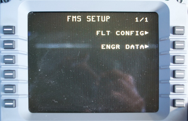
FMS Setup Page
Select FLT CONFIG (LSK 1R).
[G450 Aircraft Operating Manual, §2B-27-150, ¶8]
Set the BANK FACTOR. Enter desired bank factor into the scratch pad and line select 1L. The BANK FACTOR entry is used to set bank limits. The default is 7. Any number from 0 to 15 can be entered.
The BANK FACTOR is the highest bank angle to be used by the FMS unless a higher angle is needed to maintain protected airspace. The FMS incorporates a model of the protected airspace that includes the tighter restrictions at low altitudes and approach. The FMS checks each turn against the model and increases the bank angle above the entered BANK FACTOR, if required.
The BANK FACTOR can be entered at any time but only on the master MCDU when operating in synchronous mode. If the FMS configuration changes from single, independent, or initiated transfer to synchronous mode, the master bank factor overwrites the slave bank factor value.
This factor is only for FMS course management and has nothing to do with the guidance panel Bank Limit Select Button, which toggles between a 17° and 27° bank angle limit in the HDG SEL mode.
What to Set
[Honeywell FMS DirectTo Issue 1 (September 2009), pg. 3.] FMS Pilot Operating Tip]
Set the ‘Bank Factor’ in all CDUs to 15° (NAV, NEXT, MAINT, NEXT, SETUP, FLIGHT CONFIG) The pilot-selectable bank factor setting permits the crew to establish how aggressively the FMS will turn and therefore, how steep the bank angle will be. It is the highest bank angle to be used by the FMS (in the LNAV mode) unless a higher angle is needed to maintain protected airspace. For low settings (such as 7°), the FMS will anticipate course changes further in advance and make shallower turns. For higher values (up to 15°), the turn is initiated closer to the actual turn point and the bank angle is steeper. For most aircraft, the default factory setting is 7°. Problems arise when a pilot initiates a leg change close to the desired waypoint. When 7° is set, the aircraft will initially roll into a 7° bank which may be too shallow and results in ‘S’ turns to the waypoint. When the pilot resets the value to 15° and a leg change or sequence is made, the aircraft will immediately roll into a 15° bank toward the desired track or waypoint. This results in much more accurate turning and decreases the risk of ‘S’ turns.
Note that the pilot-entered Bank Factor setting is ignored when flying a SID, STAR approach, or when the aircraft is within 30nm (Terminal Area) of the departure/arrival airport. In this case, 20° bank is used instead. The bank factor for holding is fixed at 30°. In addition, the bank factor setting is only used for FMS guidance and does not have anything to do with localizer capture rates.
Check RAIM
Checking RAIM is fairly straight forward. For a primer on RAIM, see: Global Navigation Satellite System (GNSS) & Global Positioning Satellite (GPS) System.
System Description
[G450 Aircraft Operating Manual, §2B-17-30]
The GNSSU RAIM function ensures the integrity of the data transmitted by the device. The GNSSU has a continuous integrity level (limit) to the FMS that is used to determine if the GNSSU navigation data can be used for the current phase of flight. The GNSSU RAIM function can also detect satellite failures. It isolates and removes failed satellites when it is tracking a sufficient number of satellites for measurement redundancy.
The FMS uses predictive RAIM to determine the integrity levels at specific locations/times to support a non-precision approach and pilot's flight planning activities. The GNSSUs have the following types of RAIM predictions:
Destination
Alternate waypoint
Approach area.
The destination and alternate waypoint predictions are made at specific locations or they are the estimated time of arrival (ETA) when the FMS makes the request for flight planning purposes. Satellites can be manually deselected or enabled for destination and alternate waypoint predictions. The approach area RAIM prediction is an output of current RAIM projected 5 min into the future. Approach area RAIM is a continuous output that is performed without any interaction with the FMS.
MCDU NAV Index 1 page
Select the NAV Index page by pressing the NAV key.
Select POS SENSORS (LSK 4L)
MCDU Position Sensors page
Select GPS 1 STATUS (LSK 5R)
You could check the status of the other GPS as well.
MCDU GPS Status page
select PRED RAIM (LSK 6R)
MCDU RAIM page
You now have the RAIM check for here and now, what about there and then?
Select PILOT SEL (LSK 1R)
MCDU Pilot Select RAIM page
Enter the PLACE at LSK 1L and the time at 1R and you will be greeted with the RAIM prediction based on the downloaded GPS almanac.
Switch COM/NAV3 to DATA
Radio 1 page
Select RADIO
Select NEXT
Radio 2 page (NAV mode)
If COM/NAV3 is not in DATA mode, COM or NAV will appear in green and a frequency will also appear in green. In the example drawing, a NAV frequency is active.
While LSK 6L does not look like mode key, it is. Press LSK 6L twice to bring up the COM/NAV3 display page.
COM/NAV3 page (NAV mode)
Because there is a navigation frequency tuned, all of the prompts for DATA are missing. You need to tune a voice frequency to make them reappear. In our example the standby frequency is 118.00 so all we have to do is press LSK 2L. (If the standby frequency was also a navigation frequency we would have to enter a valid voice frequency first.)
COM/NAV3 page (NAV mode)
Once a valid com frequency is active the data prompts appear. Select DATA by pressing LSK 2R.
COM/NAV3 page (DATA mode)
At this point the page indicates COM/NAV3 is in DATA mode.
Create Stored Flight Plan
MCDU Nav Index Page 1
Select the Nav Index by pressing the NAV key.
MCDU Flight Plan List Page Example
You will see a list of previously created flight plans along with a blank entry at LSK 1L.
MCDU Flight Plan List Page With Scratch Pad Entry Example
Enter an airport pair in ICAO format separated by a dash, LSGG-KBED in the example. Press LSK 1L.
MCDU Flight Plan Select Activate Example
The MCDU allows you to activate (LSK 1R), Invert and Activate (LSK 2R), or enter performance for the stored flight plan (LSK 3R). For the sake of this example, we will activate (LSK 1R).
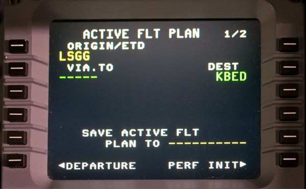
MCDU Flight Plan LSGG-KBED Example
The flight plan is now ready for further entries.
Rules for Stored Flight Plan Initialization
Rather than activate the stored flight plan you can go directly to its performance pages. The rules for this is similar to doing a "what if" exercise.
G450 Aircraft Operating Manual, §2B-26-110, ¶1.]
The initialization rules are the same as for the WHAT-IF initialization with the following exceptions:
The cruise altitude defaults to OPTIMUM, regardless of the active performance initialization. This is because the active cruise altitude may not be the best for a stored flight plan. For example, the stored flight plan may be a short leg that requires a low cruise altitude while the current flight can be flown at a high altitude and vice versa.
The takeoff fuel allowance is set to the general default. While in flight, the active and the WHAT-IF initialization both have zero fuel for the takeoff allowance.
The fuel must always be entered. This is required for computing a gross weight. Since fuel is not known at this time, a rough estimate is sufficient. When the fuel required is computed, that fuel weight can be reentered to refine the estimate, if significantly different from the entered fuel.
Once the stored flight plan data has been computed, all initialization parameters are displayed in large characters. At that point the stored flight plan initialization no longer tracks changes made to the active initialization.
When all required entries are made, the CONFIRM INIT prompt is displayed at 4R. The CONFIRM INIT prompt must be pushed to start the calculation.
Departure Coding
Navigation procedures are coded in the FMS according to the ARINC 424 specification. It isn't important to know that, other than to know there is something going on above and beyond the avionics and aircraft manufacturer. Understanding it, however, can help when trying to figure our "what's it doing now?"
Procedure Design
[Honeywell Direct-To]
The FMS is designed to process flight plan waypoints as they are defined by ARINC 424 (Navigation System Database Specification). This has led to a very reliable navigation system over a period of many years. So while airport terminal procedures grow in complexity over time, the FMS needs to accommodate change while utilizing existing software coding and specifications.
When procedures are designed, typically using PANS-OPS or TERPS, the lateral and vertical paths are defined in a manner that will provide obstacle protection. Once the procedure has been designed and approved it can then be encoded. The navigation database in any Honeywell FMS is developed using data that is supplied by a vendor. The vendor is called a Type I Data Supplier, and the two largest in the industry are currently Jeppesen and Lido. These suppliers will collect navigation data from various official state sources around the world. The data is then encoded using ARINC 424 and distributed to various users such as FMS manufacturers. The FMS manufacturers are considered a Type II data supplier, as the encoded data received must be translated into a language that can be read by the FMS. This process follows stringent requirements to ensure accuracy. Honeywell's navigation database production process has been deemed compliant with RTCA/DO-200A and FAA advisory circular AC20-153, and offers very high data integrity.
The waypoints loaded into a terminal procedure are linked together using ARINC 424 Path and Terminator, often referred to as leg types. The two elements of the Path and Terminator prescribe the way in which a path is to be flown and how the path is to be terminated.
There are several path terminators that are consistently used in procedure design. This review will cover four of the 23 different path terminators by walking through an example departure procedure. This will include the following path terminators:
VA – Vector or heading to an Altitude
CA – Course to an Altitude
DF – Direct to a Fix
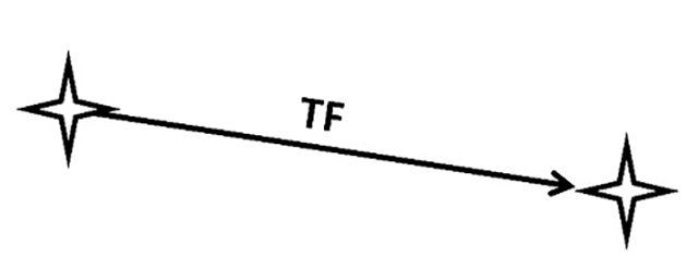
TF – Track to a Fix
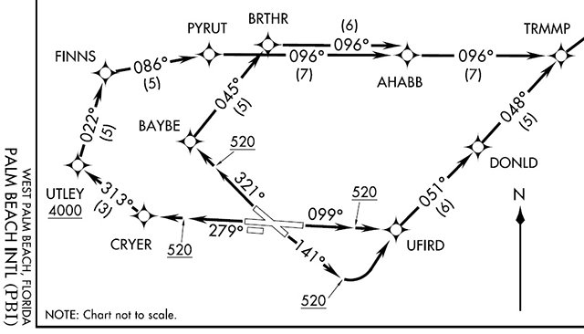
Figure 1 shows the plan view of the West Palm Beach (KPBI) IVNKA1 Departure procedure. As seen in the figure, there are four runway transitions that could be loaded into the FMS. In this example, we will first review the runway 14 transition.
Figure 1
Figure 2
Looking at the plan view (figure 1) and the textual description (figure 2) of the procedure departing from runway 14, the aircraft is to fly a heading of 141 degrees until reaching 520 feet. The procedure designer wants the aircraft to reach the specified altitude prior to making any turns. This introduces the first two Path Terminators, the VA or Vector to an Altitude (figure 3) and CA or Course to an Altitude (Figure 4). In the CA, note the addition of a red waypoint symbol. This is because the VA uses a simple Vector or Heading flown, and the CA uses a defined Course. To fly a course there must be a starting point that defines exactly where the course will be flown. There are certain FMS types that are not able to process a VA, so it will be converted to a CA by the navigation database compiling tool.
Figure 3
Figure 4
Figure 5
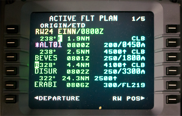
When the procedure is loaded into the NZ-2000 FMS (figure 5), it displays the waypoint *ALT01 with a course of 141 degrees and the vertical constraint of 0520A. The waypoint name, *ALT01, informs the pilot that waypoint sequencing will occur once the altitude constraint has been met. Note also, the calculated course to UFIRD is 085 degrees.
Returning to Figure 1 and 2, after *ALT01 the procedure designer wants the aircraft to proceed directly to UFIRD. Because the previous Path Terminator did not have a specified geographic location where it would terminate, due to variable aircraft climb performance, the navigation data must now command a new calculation to steer the aircraft to the desired waypoint.
Figure 6
As mentioned before, the calculated course into UFIRD while on the ground awaiting takeoff was 085 degrees (figure 5). After sequencing the altitude waypoint, the new course calculated to UFIRD is 074 degrees. This is because the actual distance to reach the altitude was farther than the calculated distance. In other words, it essentially took the aircraft longer to reach the altitude than predicted. In the example, after take off and sequencing the altitude waypoint, if the next (TO) waypoint is encoded with a DF as the path terminator (Figure 6), the FMS will calculate a path from the current position of the aircraft directly to that waypoint. Keep in mind that intercept algorithms provide a smooth turn to the waypoint and help reduce the S-turning to rejoin a path that could now be behind the aircraft.
Figure 7
Figure 8
The Track to a Fix or TF path terminator (Figure 8) simply tells the FMS to connect one fix to the next by using a great circle route. It is the simplest of path terminators and is very commonly used to link waypoints together. Procedure designers can position waypoints using latitude/longitude and use TF path terminators thus allowing the FMS to connect them.
Figure 9
Looking at the database coding in Figure 9, the path terminators are listed in the PT column, the course and heading under Cs/Hd, and the altitude is listed under Alt1.
Download Flight Plan
The download flight plan procedure is easy enough, except when the downlink is not available. You will need line of sight with either a VHF ground station or an INMARSAT satellite. Patience is usually enough to achieve this. Where does the flight plan originate? The usual suspects are GDC and ARINCDirect but you can use other vendors too. Just make sure they send the flight plan to GDC with a recall number that is GDC/Arinc compatible.
Data Link Service Provider Line of Sight Limitation
[G450 Aircraft Operating Manual, §2B-21-40, ¶1.]
By default, the PLANEVIEW CMF communicates by way of the land-based ACARS VHF network, which includes the Aeronautical Radio, Inc. (ARINC) and SITA subnetworks. Based on position information provided by the aircraft FMSs, the CMF automatically tunes to the appropriate subnetwork. In areas where VHF coverage is unavailable, the CMF may use the Inmarsat Aero-H, Aero-H+, or Aero-I satellite UHF networks. This provides both packet mode (datalink) and circuit mode (voice and data) capabilities to the aircraft. The CMF switches to and from the satellite UHF network based on the availability of land-based VHF network coverage.
As a provider of flight support services, the GDC is at the hub of the system. In addition to performing host processing for CMF datalink message traffic, the GDC has telephone, fax, and network connections to domestic and international ATC facilities, fixed-base operators (FBO), multiple weather providers, and customer flight departments.
All PLANEVIEW CMF transmissions, whether VHF or satellite, require line of sight to a VHF ground station or Inmarsat satellite, respectively. Refer to the map of GDC datalink coverage, shown at the end of this section.
Establishing and maintaining line of sight is most often a concern when transmitting VHF on the ground due to the curvature of the Earth, high surrounding terrain, and man made structures. VHF transmissions from many airports are simply not possible because the nearest VHF ground station is below the horizon or blocked by surrounding terrain. Even at airports with on-airport VHF ground stations, VHF transmissions from certain areas of the airport may not be successful due to man made structures obstructing line of sight. In flight, VHF coverage is normally excellent, although coverage limitations may exist in remote areas of the world or at low altitudes.
Transmitting by way of satellite while on the ground is generally reliable. Although, line of sight issues may still arise due to surrounding terrain and man made structures because the Inmarsat satellites are in an equatorial geostationary orbit. In flight, the curvature of the Earth is a concern only at latitudes greater than 70° North or South. Except at these high latitudes, satellite coverage while in flight is seamless.
You may notice there are certain airports and locations at certain airports that are slower to allow a downlink than others. It may very well be that ground obstructions and normal satellite orbits will routinely give you slower downlinks. You may just have to plan on more time at these locations. We've never failed to get a connection and it has never taken more than five minutes.
G450 Procedure: Download Flight Plan
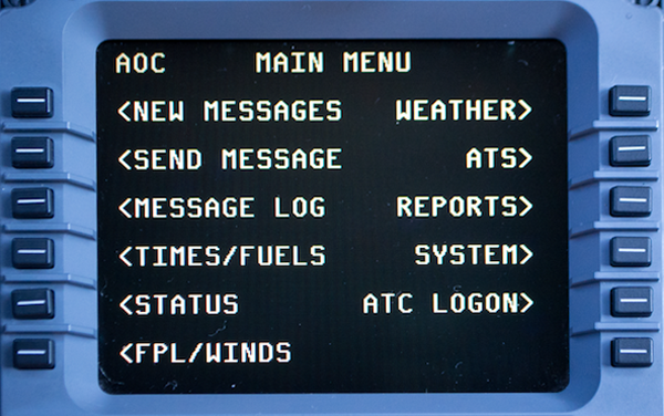
Photo: MCDU AOC Main Menu Page
Select the AOC Main Menu by pressing DLK.
Everything on this page comes from your data service provider (GDC or ARINC).
Select FPL/WINDS (LSK 6L)
Photo: MCDU DATALINK INDEX Page 1
Select FLT PLAN (LSK 1L).
Photo: MCDU DATA LINK FLT PLAN Request Page, by Flight Plan Number
Enter the flight plan number in the scratch pad and press LSK 2L. Alternatively, you can press LSK 1R and enter the to and from ICAO identifiers and ETD.
Photo: MCDU DATA LINK FLT PLAN Request Page, Flight Plan Number Entered
Select SEND REQUEST (LSK 6R)
Photo: MCDU FLT PLAN RECEIVED prompt
Once the FLT PLAN RECEIVED prompt is received, return to this page and select FPL REVIEW (LSK 5R)
Photo: MCDU DATALINK FPL REVIEW Page Example
You can review the entire flight plan using the NEXT and PREV key and complete the download by selecting ACTIVATE (LSK 6R)
Holding Pattern
Holding Pattern Description
[G450 Aircraft Operating Manual, §2B-27-130, ¶3.]
The HOLDING PATTERN page is used to define and review holding patterns. Holding quadrant, inbound course, turn direction, and leg length or time of the inbound leg of a holding pattern can be defined on the HOLDING PATTERN page.
he default holding is a standard holding pattern at the designated holding fix with the inbound course set to the flight plan course into the holding fix. Leg times are defaulted to 1 min below 14,000 ft and 1.5 mins at or above 14,000 ft.
G450 Procedure: Holding Pattern Definition and Review
Photo: Example Flight Plan
Press the DIR key.
Photo: Example Flight Plan With DIRECT Prompt
DIRECT will appear on the top, press PATTERN (LSK 6L).
Photo: PATTERNS page
Press HOLD (LSK 1L).
Photo: Example Flight Plan With HOLD
"*HOLD*" appears in the scratch pad, enter this on the desired holding point using a left LSK. In our example we are holding at DPK so we press LSK 4L.
Photo: Select Hold Page Example
Select the desired direction of turn: LSK 1L for right and LSK 2L for left.
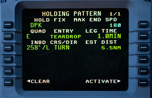
Photo: Holding Pattern Definition Page
You can adjust any of the parameters in green and select ACTIVATE (LSK 6R).
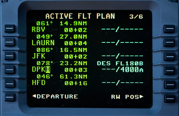
Photo: Example Flight Plan with DPK Hold
The holding pattern is denoted by an "H" and you will see the result on the navigation display as shown on the top of this page.
Initialize Position
There isn't much to this if your normal ramp position gives you a good shot of the GPS satellite constellation. If your GPS usually takes a while to come up, you can speed things up by defining a pilot waypoint RAMPX, where the X can be any letter from A to Z or number from 0 to 9. The FMS will offer that point to you as a choice if you start the airplane up within 3 NM of that position. Normally, however, once the GPS figures out where it is you are better off selecting it.
Inertial Reference Position Initialization
[G450 Aircraft Operating Manual, §2B-14-20]
The IR component requires system initialization (entry of latitude and longitude). Initialization can be done using either the flight management system (FMS) input that is manually entered by the crew through the multipurpose control display unit (MCDU) or automatically from the global positioning system (GPS). A pilot-entered position has priority over a position from a GPS.
To initialize the FMS position, select the POS INIT line select switch prompt from either the NAV IDENT or POS SENSORS page.
G450 Procedure: Initialize Position
Photo: MCDU Nav Ident Page, from Eddie's aircraft.
When you first bring power to the aircraft using the emergency batteries, MCDU 1 should display engine instruments and MCDU 3 should show the emergency radio page. MCDU 2? It's got nothing.
After you bring the rest of the electrical system up, MCDU 2 comes up with the screen shown above. You can bring the other two MCDUs to the same screen by selecting NAV > NAV IDENT.
[G450 FMS QTL, Nav Ident
Check/Correct the Date.
Check/Correct the GMT.
The time and date come from the GPS but can be corrected if the GPS doesn't come up.
Verify SW
The software identifier has been NZ7.1 for a while.
Verify Active NDB.
Unlike previous Gulfstreams, the alternate data base will come up automatically if the active data base is expired and the alternate is current.
Turn the IRS's ON.
Select POS INIT (LSK 6R)
Photo: MCDU Position Init Page, No Present Position
[G450 Aircraft Operating Manual, §2B-27-160
1L and 1R - The last FMS position is displayed when the aircraft is on the ground. If the line select key adjacent to the LOAD prompt (1R) is pushed, the FMS is initialized to that position.
2L and 2R - The reference waypoint (REF WPT) line is below the last FMS position. This line can be filled automatically by the FMS or the pilot can make an entry at any time. In order of priority, the FMS fills in this line as follows:
RUNWAY THRESHOLD - If a departure runway has been selected in the active flight plan, the coordinates of the runway threshold are displayed. Using this feature, runway position can be updated when the aircraft is at the end of the runway ready for takeoff.
RAMPX WAYPOINT - If there is a last position available, the FMS compares the last position to the list of RAMPX waypoints. RAMPX waypoints are pilot-defined waypoints with the name of the RAMP plus any alphanumeric (0 through 9, A through Z) character. If one (or more) is found within 3 NM of the last position, the closest one is displayed. If more than one RAMPX waypoint is defined for the same airport, the FMS selects the closest one to the last position. If multiple RAMPX waypoints are defined with the same latitude/longitude, the FMS selects the one with highest alphanumeric priority.
AIRPORT REFERENCE POINT (ARP) - If there is a last position available and no RAMPX waypoints are found within 3 NM, the FMS displays the closest ARP within 3 NM.
PROMPTS - If none of the above waypoints are displayed, the FMS displays prompts.
3L and 3R - The position of the highest priority GPS is displayed. The priority order, from highest to lowest, is as follows: GPS 1, GPS 2, GPS 3. This order of priority applies to all FMSs. If the line select key adjacent to the LOAD prompt (3R) is pushed, the FMS is initialized to the GPS position.
Photo: MCDU Position Init Page, Loaded
[G450 FMS QTL, Position Initialization]
The selected position becomes the FMS position.
"(LOADED)" is displayed above the coordinates selected.
If not in SYNCHRONOUS mode Each FMS position must be initialized.
[G450 Aircraft Operating Manual, §03-03-10] Initializing the position on any MCDU / FMS results in initializing the position for all FMSs.
Lateral Offset
Sometimes you need a Strategic Lateral Offset Procedure (SLOP); fortunately you have an easy way to do that in the G450. Can you SLOP with ADS-C? The ICAO says you should, but only in the North Atlantic is it actually in writing that you can.
Photo: MCDU Progress 3/3 Page
Enter Lateral Offset
[G450 Aircraft Operating Manual, §2B-29-20, Procedure 1]
Select PROGRESS page 3
Enter lateral offset into the scratch pad. Enter direction (L or R) and distance in nautical miles.
The decimal is optional. Examples: L1, R1.5, L10, etc.
Enter the offset by pushing line select 1R.
[G450 Aircraft Operating Manual, §2B-31-20, Table 1]
The minimum entry is L or R plus one digit
Range is 0.1 to 30.0 NM in 0.1 increments
[G450 Aircraft Operating Manual, §2B-29-20, Procedure 1] To manually cancel the lateral offset waypoint, push the DEL key and line select *DELETE* to 1R.
Entering / Exiting an Offset from the Map Display
[G450 Aircraft Operating Manual, §2B-07-20, ¶3.M.]
When the cursor is positioned over the aircraft symbol, the aircraft symbol is highlighted by a blue circle. In this situation, the immediate action task menu is displayed by pushing the ENTER switch on the CCD. The task menu contains the following menu items:
PPOS Hold
Offset, Exit Hold (if holding) or
Resume Hold (if exiting hold) or
Cancel Offset (if offset active).
Selecting Offset from the immediate action menu displays the Offset dialog box. The Offset dialog box is an interface to define/activate lateral offsets on the active FMS leg. The box contains an Offset title positioned in the upper left corner. Two data boxes are displayed on either side of the dialog box labeled Left and Right above them and NM to the right. These data boxes are initially dashed-out. A vertical line is displayed in the middle with a waypoint symbol at the top. A small aircraft symbol is displayed and positioned initially above the data boxes on the vertical line. When the cursor is positioned in the proximity of either the left or right data box/label, a small curly cue is displayed inside the data box and a blue box is drawn around the box/label.
When the MFK is rotated, the data displayed in the box increases or decreases in the range of 0.1 to 30.0 NM in 0.1 NM steps and the aircraft symbol moves laterally in the direction of the change.
The Delete/Apply buttons are displayed in the lower left/right portions of the box respectively, as shown in Figure 40. When Apply is selected, the FMS activates the prescribed offset immediately and the box is removed. If an offset exists for the active leg when Offset is selected, the Delete box remains available and when selected, cancels the offset. If the cursor is moved off the dialog box, the box closes after the time-out period and no action is taken.
The Cancel Offset menu item is displayed in the Immediate Action menu if an offset exists. When selected, the Cancel Offset item cancels the offset. Subsequent to defining a Vectors To Final transition, when the FMS transitions to terminal mode, the Activate Vectors task menu item is available in the immediate action menu. When selecting the Activate Vectors task menu item, the FMS activates the Vectors To Final. The Activate Vectors task menu item is available in the Aircraft Task menu if no transition is in the approach procedure and the FMS transitions to terminal mode.
Offset Indication
[G450 Aircraft Operating Manual, §2B-25-10, ¶9.] OFFSET is an advisory (white) annunciator. The annunciator is displayed when a lateral offset has been entered on the PROGRESS 3 page or graphically. The annunciator is removed or turned off when the offset is removed.
Offsets Prohibited
[G450 Aircraft Operating Manual, §2B-29-20, Procedure 1] Lateral offsets cannot be entered while flying any of the following:
SIDs, STARs, approaches
Patterns
In the terminal area (10 NM from origin, 25 NM from destination)
In the polar region.
Offsets Automatically Cancelled
[G450 Aircraft Operating Manual, §2B-29-20, Procedure 1]
Offsets are automatically canceled for the following:
Course changes greater than 90°
SIDs, STARs, approaches
Patterns
Intercepts
An OFFSET CANCEL NEXT WPT message is displayed before offset is automatically canceled.
ADS-C Notes
[Gulfstream Operating Manual Supplement OMS-3, ¶5.] The following is a clarification of FMS operation when flying an offset path:
For ADS reporting of present position at a waypoint sequence, the FMS position will correctly report the offset position
For operation using the NAT Strategic Lateral Offset Procedures (SLOP), the entry of a right one or two NM offset will have negligible effect on the FMS predictions at the next and next + 1 waypoint
For a larger than 2 NM offset, e.g. for a weather deviation, the FMS predictions assume that the aircraft will return to the original flight plan prior to the next waypoint. If this is not the case, the crew should advise ATC that the FMS predictions are to the original path and not the offset path.
ADS-C complicates things a bit, since it continuously reports the aircraft's actual position, with or without SLOP. You are clearly allowed to SLOP with ADS-C in the North Atlantic. Elsewhere? The ICAO clearly supports the SLOP concept and the list of countries allowing the practice is growing. But you cannot assume everyplace in the world is okay with it.
CPDLC Notes
Photo: MCDU Nav Index
[G450 Aircraft Operating Manual, §2B-33-70, ¶4.] If the aircraft is flying an offset path and the downlink message contains any of the following message elements: ASSIGNED ROUTE, NEXT WAYPOINT, ENSUING WAYPOINT or POSITION REPORT, the downlink message also includes the following message: DEVIATING [distance offset] and [direction] OF ROUTE (e.g., DEVIATING 3NM NORTH OF V58)
You can access the G450 CPDLC system by pressing the NAV key and then selecting ATC (LSK 1R)
Select ATC Request (LSK 2L)
Photo: MCDU ATC Index
[G450 Aircraft Operating Manual, §2B-33-140] The ATC REQUEST page gives access to more detailed request pages. Entry of a value to a request altitude, speed or offset results in the display of the detailed altitude, speed or offset request pages.
Lateral offset requests are displayed in Line 1R. When a message element containing a request for a lateral offset is included in the downlink message, the offset value associated with the message is displayed in line 1R.
Valid entries in line 1R are the letters L or R followed by a numerical distance (1 to 30). Valid entries result in the display of the ATC OFFSET REQUEST page with the entered offset value. Entry of a valid offset over an existing offset results in the deselection of the previous message element and any associated requests. Deletion of an entered offset value results in the deselection of any message element containing a request for a lateral offset and any associated offset elements.
Dashes are displayed in line 1R when a lateral offset request has not been selected.
[G450 Aircraft Operating Manual, §2B-33-160]
Line 1L
Line 1L displays the offset entered on either the ATC REQUEST page or on the ATC OFFSET REQUEST page. An entry to line 1L results in the message element REQUEST OFFSET [direction][distance offset] being included in the downlink message.
Valid entries to line 1L are the letters L or R followed by a numerical distance (1 to 30). Entry of a offset value results in any previously entered offset value being deleted and any previously selected offset request message element and associated offset request message elements being deleted.
Deletion of an offset value results in any previously entered offset value being deleted and any previously selected offset request message element and associated offset request message elements being deleted.
Dashes are displayed in line 1L when an offset entry is not valid.
Line 1R
Line 1R displays the time or position corresponding to an offset request when an offset is displayed in line 1L. A position (waypoint) entry to line 1R includes the message element AT [position] REQUEST OFFSET [direction] [direction offset] in the downlink message. A time entry to line 1R includes the message element AT [time] REQUEST OFFSET [direction] [distance offset] in the downlink message.
An entry to line 1R must be in the format of time (HHMM) or position (waypoint). An entry to line 1R is rejected if the entry is not recognized as either a valid time or position.
Selection of the DUE TO WEATHER prompt results in two possible message elements being included in the downlink message.
AT [position] REQUEST OFFSET [direction] [distance offset] DUE TO WEATHER
AT [time] REQUEST OFFSET [direction] [distance offset] DUE TO WEATHER
Performance Initialization
Photo: MCDU PERF INDEX 1
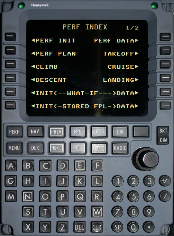
Select the PERF INDEX by pressing the PERF key.
Select PERF INIT (LSK 1L).
Photo: MCDU PERFORMANCE INIT 1
Select the next page by pressing NEXT.
[G450 Aircraft Operating Manual, §2B-26-30, ¶1.]
1L — Aircraft Type (ACFT TYPE) is displayed on this line. No entry is permitted here. The aircraft type is loaded from the aircraft database. If no aircraft database has been loaded, this line is blank. An aircraft database must be loaded in order to select the FULL PERF option. Normally, an aircraft database needs to be loaded only when the FMS is installed. The aircraft database is retained from flight to flight and updated by the learning process. The pilot should verify that the ACFT TYPE data field has the correct aircraft type. The system generates incorrect performance predictions if the FMS contains the wrong AIRCRAFT DB.
1R — Aircraft tail number (TAIL #) is displayed on this line. The tail number must be entered in this field before going to the next page. Once entered, it is saved. No action is required on future flights.
2L — The FMS has three PERF modes or methods of performance calculations. Use the OR prompt at 2R to change the modes
When CURRENT GS/FF (groundspeed/fuel flow) is selected, performance calculations are based on current groundspeed and current fuel flow. However, while on the ground, the FMS default groundspeed is used. This groundspeed is displayed at 1Ron the first page of any stored flight plan. Once airborne, the current groundspeed is used. The current fuel flow is displayed at 1R of the FUEL MGT 1/2 page. However, the value can be overridden by a pilot entry. The overridden value is then used.
Selecting PILOT SPD/FF bases performance calculations on pilot-entered speed schedules and cruise fuel flow. When using this option, the cruise fuel flow must be entered at 2R on the PERFORMANCE INIT 2/4 page. Automatic adjustments are made for the higher fuel flow in climb. Entered winds and sensed winds (once airborne) are included in the groundspeed predictions used for time en route estimates.
Selecting FULL PERF bases performance on pilot selections and the aircraft performance. An aircraft database must be loaded before this option is available
I can think of only one scenario where you would not use FULL PERF: if the performance database was missing.
Photo: MCDU PERFORMANCE INIT 2
Select the next page by pressing NEXT, unless you want to make a change to the indicated speeds.
[G450 Aircraft Operating Manual, §2B-26-30, ¶1.]
1L and 3L — The climb and descent speed schedules are always displayed as both a calibrated airspeed (CAS) and a MACH. Changes can be made by entering a CAS, a MACH, or both separated by a slash (/). The leading slash (/) is used as an option when entering a MACH only. Entering *DELETE* returns the default climb or descent speed schedule. The active speed command is the CAS at lower altitudes and MACH at higher altitudes. The crossover altitude is where both the CAS and the MACH translate to the same true airspeed (TAS). The FMS always uses the CAS or MACH entry that provides the lowest TAS at the current altitude.
2L — The cruise speed schedule can be a CAS/MACH pair, only CAS, only MACH, or a system-generated cruise speed schedule. Entries of a CAS, a MACH, or both are accepted. Entering *DELETE* returns the default cruise speed schedule which is LRC in FULL PERF and the value from the aircraft database (or 300/.80) in CURRENT GS/FF or PILOT SPD/FF. The two other system-generated schedules, MAX SPD, MAX END and MXR SPD, can be selected on the CRUISE MODES page only. If both a CAS and MACH are entered, the active speed command is the CAS or MACH that provides the lowest TAS at the current altitude. If the LRC or MAX SPD schedules are active, the speed command is issued as a MACH at higher altitudes and a CAS at lower altitudes. This is determined by the VMO/MMO crossover altitude. If the cruise speed schedule is MAX END, the speed command is always CAS.
The defaults work well but you may consider reducing the descent angle from 3.0 to 2.5 degrees if your ATC environment permits it. The G450 cannot descend at 3.0° at high altitude without picking up speed or introducing extra drag.
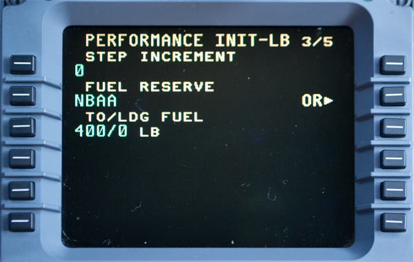
Photo: MCDU PERFORMANCE INIT 3
Select the next page by pressing NEXT, unless you want to make a change to the step increment, fuel reserve, or to/ldg fuels.
[G450 Aircraft Operating Manual, §2B-26-30, ¶1.]
1L — Entries for step increment must be in thousands of feet. The three trailing zeros can be omitted. For example, a 4000 ft step climb increment can be selected by entering 4 or 4000. Entering *DELETE* returns the selection to no step or zero feet. Step climbs are used for long range flights to optimize the aircraft performance. As the aircraft burns fuel, the optimum altitude goes up. If a step increment is selected, the FMS computes the bottom of step climb (BOSC) point. The BOSC is where the aircraft is light enough to climb by the amount of the step increment to a new cruise altitude. More than one step climb can be calculated for a flight. When a step increment is selected, time and fuel predictions assume that the step climbs will be made. Therefore, a step increment should only be selected when the intent is to make the step climbs. If clearance is not given or the step climb is not going to be made, step increment should be set to zero in order to maintain accurate time and fuel predictions.
You will almost never be permitted a step climb on your terms so you should probably leave this number alone. We used this in the GV rather than look at "Check Fuel Remaining" messaged for the first few hours. If you use this feature, you just have to be aware that there are caveats to your fuel planning.
2L — The method of calculating fuel reserve is displayed on this line. Entering *DELETE* returns to the default reserve mode which is National Business Aircraft Association (NBAA) rules.
The NBAA fuel reserve requirement is the sum of the two following items:
Fuel required to fly the alternate flight plan (from the destination to the alternate destination). If the alternate flight plan is less than 200 NM or if there is no alternate flight plan, the NBAA standard 200 NM alternate flight plan is assumed.
Fuel required to hold for 30 min at 5000 feet at the reserve holding speed at the alternate.
A fuel reserve in pounds can be entered. The specified fuel reserve applies at the destination, or at the alternate destination if one has been entered.
A fuel reserve in minutes can be entered. The time entered is converted to pounds of fuel assuming flight at 5000 feet at the reserve holding speed. The fuel reserve applies to the destination or the alternate destination if one has been entered.
3L — The default values of takeoff/landing fuel (TO/LDG FUEL) are supplied from the aircraft database. However, manual entries can be made. Manual entries are saved for the next flight. Entering *DELETE* returns the default values. The takeoff fuel allowance includes fuel burn for taxi and takeoff. Takeoff fuel allowance is decremented by fuel flow. However, it is not decremented past zero. Following takeoff or when the takeoff allowance has been decremented to zero, fuel remaining values are adjusted to account for actual fuel burned. The takeoff fuel allowance is added to the fuel required calculation. The fuel required calculation is the predicted fuel from takeoff to landing plus reserves. The landing fuel allowance is a buffer amount of fuel that the FMS incorporates into the total fuel required computation. The landing fuel is intended to cover the ground operation after landing. The value can be changed at any time.
Photo: MCDU PERFORMANCE INIT 4
[G450 Aircraft Operating Manual, §2B-26-30, ¶1.]
1L — The transition altitude can be entered here. The FMS uses the input to determine how to display altitudes. Altitudes above the transition altitude are displayed as flight levels (FL) and below in feet. Entering *DELETE* returns the default value of 18,000 feet.
This entry has nothing to do with when you get the "Check Transition Altitude" warning, only when the FMS decides to list an altitude in feet or flight levels.
1R — Speed limits associated with altitudes, not waypoints, can be entered. For U.S. operation, 250 knots below 10,000 feet is entered. The FMS speed command is limited to this speed below the restriction altitude. Entering *DELETE* removes the speed/altitude limit and displays dashes. This is the only field that can be left with dashes and still allow performance data to be computed.
2L — INIT CRZ ALT (Cruise Altitude) -- The initial cruise altitude is entered at this location. The FMS uses the initial cruise altitude to determine the altitude where the cruise phase of flight commences. The FMS changes the speed command and EPR rating from climb to cruise when the aircraft levels at the initial cruise altitude or higher. The default for INIT CRZ ALT is OPTIMUM if the performance mode is FULL PERF. The FMS calculates the optimum cruise altitude based upon the performance initialization data. After performance initialization is completed, the calculated optimum altitude is displayed in small characters on this page. The method used to compute the initial cruise altitude is displayed following the altitude.
You should always enter your planned initial level off altitude here. The FMS will not sequence to cruise mode until you reach this altitude.
Photo: MCDU PERFORMANCE INIT 5
[G450 Aircraft Operating Manual, §2B-26-30, ¶1.]
1L — Basic operating weight (BOW) is retained in memory but it should be verified on each flight. A new entry can be made at any time. Entering *DELETE* returns the entry prompts.
2L — The fuel weight, when sensed by the fuel quantity system, is displayed in small characters. The pilot can manually enter a fuel weight which is displayed in large characters.
If the fuel truck hasn't arrived yet, you have two viable options:
Enter the exact amount showing on the fuel gauge (or leave it alone if it is already accurate). The fuel total should update as the fuel quantity increases, as will your takeoff and landing data (TOLD). But you won't have an accurate TOLD until then.
Enter your planned fuel load. The TOLD will give you good information, provided you end up with the predicted amount of fuel. But if your fuel load ends up different, your TOLD will be inaccurate because the fuel quanity may not reflect your actual fuel quantity. The biggest danger here is your critical TOLD numbers will be too low for your actual weight.
3L and 1R — Cargo weight and passenger count must be entered in order to compute performance data. The average weight per passenger can also be adjusted by entering a slash (/) followed by the weight (e.g., /200).
6R — When performance initialization is complete, the CONFIRM INIT prompt is displayed in the lower right corner of this page. The CONFIRM INIT prompt must be selected for the performance function to calculate performance data and for the VNAV function to be available. Selecting the CONFIRM INIT prompt displays the PERF DATA page. After confirming initialization, the prompt at 6R of the PERFORMANCE INIT page becomes PERF DATA on all PERF INIT pages.
Once you've initialized the performance, you will never see the CONFIRM INIT prompt again unless you start over. From this point, changes to parameters will result in instant changes to output calculations.
Optimum Altitude
[G450 Aircraft Operating Manual, §2B-26-30, ¶1.]
The optimum altitude has different definitions based on the cruise speed mode. For the LRC and manual cruise speeds, the optimum altitude is where the specific range is optimized. This altitude is typically close to the ceiling altitude. The MAX SPD optimum altitude is where true airspeed is maximized. This altitude tends to be close to the VMO/MMO crossover altitude. For MAX END speed, the optimum altitude is where the fuel flow is minimized. For MXR SPD, the optimum altitude is where true airspeed is maximized while ensuring the destination can be reached based on fuel quantity.
The OPTIMUM altitude is short-trip limited. This means the computed altitude is adjusted downward if the flight is not long enough for a climb to the optimum altitude. Regardless of short-trip limiting, the cruise altitude is always set at least as high as the altitude selector.
The altitude labeled as "Optimum Altitude" is almost always a lie. You rarely, if ever, fly at LRC, MAX SPD, or MAX END. And even if you did, setting the Altitude Selector above the computed altitude overrides it.
Pre-Departure Clearance (PDC)
The G450 Pre-Departure Clearance (PDC) request depends on your main operating software version. The following is based on having ASC 910 installed, so it isn't documented in the current (Jan 2014) aircraft operating manual. What about a domestic CPDLC Departure Clearance instead? See: PDC versus DLC.
PDC Explained
[G450 Aircraft Operating Manual, §2B-21-40, ¶2.E.]
PDCs are departure clearances received by way of datalink and are available at many airports in the United States to PLANEVIEW CMF-equipped aircraft. The aircraft, including any variable callsigns, must be registered through the GDC with the FAA, and ARINC. Use of PDCs at participating airports is mandatory once registered. Refer to the list of participating airports at the end of this section.
A PDC is based on a filed instrument flight rule (IFR) flight plan, regardless of whether the flight plan was filed by the GDC, through a flight service station (FSS), or by way of direct user access terminal service (DUATS). Approximately 20 min prior to the filed time of departure of the flight plan, ATC will generate and then forward the PDC to the GDC for storage. With this in mind, request the PDC no earlier than 15 min prior to the filed time of departure. Because this short time is often insufficient to receive the clearance and depart as planned, the GDC recommends filing the flight plan with a time of departure 30 min earlier than the actual intended time of departure. Refer to the PDCs procedure described later in this section for detailed instructions to request a PDC.
If the GDC has received the PDC from ATC, the PDC is sent to the aircraft as a datalink message. If the GDC has not received the PDC from ATC, a datalink message indicating that the PDC has not been received from ATC and that the PDC may be requested again in 5 min is sent to the aircraft. Multiple PDC requests can be sent until 10 min prior to the filed time of departure.
Once the PDC is received, the flight crew is required to follow the clearance. Be sure to page forward through the clearance until END OF CLEARANCE is displayed. An aircraft can receive only one PDC per airport per day and a PDC will not be available if there is any change to the filed route and/or altitude or if the clearance needs to be negotiated. A PDC is valid for 2 hr beyond the filed time of departure.
It is up to the airport tower facility to actually send the PDC, they seem to do this about 30 minutes prior to your filed time.
G450: Requesting PDC (Departure Clearance)
Photo: AOC Menu Page
Press the DLK key to access the AOC Menu Page.
AOC is "Aeronautical Operational Communications" and refers to any communications between you and your data service provider, usually ARINC or GDC.)
Select ATS (LSK 2R)
Photo: ATS Menu Page
Select DCL REQ (LSK 3L)
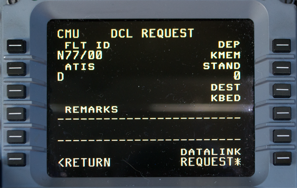
Photo: DCL Request Page Blank
Enter the flight ID at LSK 1L. Note the default format will be - - - / - - - where you appear to be given the option of entering three characters either side of a slash. You enter your flight ID as follows:
For a flight ID with three characters enter ##/#, for example N1A would be N1/A
For a flight ID with more than three characters enter ###/##, for example N1234A would be N12/34A
In the drawing, N7700 is entered N77/00.
The page should remember your FLT ID from one flight to the next.
The ATIS can be A for arrival or D for departure.
Notice the STAND entry at LSK 2R is blank. You will not get an asterisk at LSK 6R until you fill this out with something, even if you have to make the something up.
Photo: DCL Request Page Ready
With a stand number of 0, the asterisk at LSK 6R appears and we can request our PDC. I've also used "FBO" as the stand and that worked too.
Set RNP
Set RNP
The Required Navigation Performance (RNP) on your Pilot Flight Display is set automatically by the FMS to agree with the airspace you are flying and the phase of flight (depature, en route, approach) and you will rarely need to adjust it. But, for example, you are flying a narrow navigation cooridor and want to be alerted well before getting out of limits, setting a lower value can be useful. When you exceed to limits, the RNP display and the course deviation indicator turn amber.
Select Progress 1/3 (Press PROG key)
Select Progress 2/2 (Press NEXT)
Photo: MCDU Progress 1 Page
Photo: MCDU Progress 2 Page
Select RNP (Press LSK 6L)
Photo: MCDU RNP Settings Page
Enter your desired RNP into the scratch pad.
Press LSK 1L
Photo: MCDU RNP Settings Page
The new RNP setting (0.50 in our example) should appear at LSK 1L.
The settings reported in the other positions are automatically used when the conditions are correct. All of these are self explanatory except the "RAD" postion, which is the default RNP value used on FMS approaches overlaying "radio" approaches, such as a VOR or NDB approach that does not include "GPS" in the title.
True/Magnetic Selection
The airplane knows when it needs to use true heading instead of magnetic heading and will make the switch for you. There is a procedure to allow you to make the change manually, shown below. There are a lot more things to consider when this happens.
Limitations
[G450 Airplane Flight Manual, §1-03-10, ¶6.]
TRUE heading must be selected prior to N73° and S60° Latitude.
Operation must be conducted in accordance with the guidance and limitations expressed in Section 01-34-30, Flight Management System (FMS).
[G450 Airplane Flight Manual, §1-34-10] Honeywell HG2100AB and HG2100BB Series IRS equipment installed in the Gulfstream G450 has been certified for alignment to 78° Latitudes. For alignment between 70° and 78° Latitude, fifteen (15) minute alignment time is required. For flight above 73° N and 60° S Latitude, EFIS heading information must be switched from magnetic (MAG) to TRUE due to loss of valid MAG heading from the IRS.
True/Magnetic Automatic Selection
[G450 Aircraft Operating Manual, §03-08-310]
When flying above the latitude for a valid mag heading, the FMS automatically switches to true heading. The MCDU scratch pad message ACTIVE MODE IS TRUE HDG is provided.
When flying below the latitude for a valid mag heading, the FMS automatically switches back to mag heading (if mag heading is selected on the MAINTENANCE 3/3 MCDU page). The MCDU scratch pad message ACTIVE MODE IS MAG HDG is provided.
True/Magnetic Pilot Selection
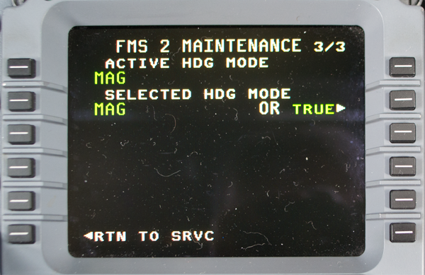
Photo: MCDU FMS Maintenance Page 3/3
[G450 Aircraft Operating Manual, §2B-27-150 ¶4]
If TRUE is the active mode, all courses and headings displayed by the FMS are followed by the letter T. If MAG is the active mode, all courses and headings displayed by the FMS are followed by a degree symbol (°) on the FMS pages.
The active mode also reflects how courses are displayed on the HSI. If the FMS is selected as the navigation source for the HSI, the course displayed by the FMS is relative to the mode that is displayed for the ACTIVE HDG MODE on this page.
The pilot can toggle between magnetic and true by pushing the line select key at 2R.
High Latitude Flying
[G450 Aircraft Operating Manual, §2B-27-150 ¶5]
Entering the polar region (above 89° N or below 89° S) results in the message ENTERING POLAR REGION being displayed. When entering the polar region, the FMS uses its highest priority sensor for navigation. Sensor blending is suspended and the FMS position is slowly ramped to the position of its highest priority sensor. Under normal circumstances, this means that FMS 1 uses IRS 1, FMS 2 uses IRS 2 and FMS 3 uses IRS 3. If the highest priority sensor has failed, the next priority sensor is used. The POS SENSORS page indicates which sensor is being used.
Under normal operations, the onside IRS is used as the heading source by EFIS (IRS 1 for the pilot and IRS 2 for the copilot). If the EFIS and FMS are using the same IRS, the EFIS will display a 180° reversal at the same time the FMS crosses the pole.
When leaving the region (below 88° N or above 88° S), the message EXITING POLAR REGION is displayed. The FMS resumes sensor blending and slowly ramps from the high priority sensor position to the blended sensor position.
The plan mode for the EFIS map display is not useful while at or near the pole. The information presented is correct, but the presentation is not useful because the plan mode is presented North up. When at the North pole for example, everything is South. Therefore, the plan mode must not be used during operations at or near either pole. Instead, use the regular map mode.
Correctly flown holding patterns are possible while in the polar region. However, the EFIS airplane symbol does not always show on the holding pattern. The display error is more pronounced the further away the aircraft is from the holding fix and/or the closer the aircraft is to the pole. If a holding pattern is hand flown in the polar region, the HSI presentation should be used for required track and deviation.
Since the FMS uses the highest priority IRS (GPS if no IRS is available) and the IRS position cannot be updated, manual FMS position update is not permitted in the polar region.
During operations in the polar region, FMS lateral offset is inhibited. Any entered lateral offset is removed when entering the polar region.
Update Winds
If you don't have accurate winds in your flight plan, you don't really have an accurate flight plan. There isn't much about how to do this in the manual and the fact there are two methods makes it even more confusing. You may need both methods, though one is arguably better than the other. (Especially if you are crossing an ocean and the winds are critical.)
Photo: PERF Index
The operating manual is silent on how do to this, but it does point you in the right direction. To access the flight plan winds, press the PERF key and from that menu select PERF PLAN (LSK 2L)
Photo: MCDU PERF Plan
[G450 Aircraft Operating Manual, §2B-26-50] The PERF PLAN pages display the estimated fuel remaining and ETE for each leg of the flight, as shown in [the figure]. No flight plan changes can be made from this page. The PREV and NEXT keys are used to review the entire flight plan. In addition to this information, this page shows a wind/temperature (W/T) prompt (right line select) for each waypoint.
Photo: MCDU Wind/Temp page
The operating manual shows that each value can be changed manually but does not show the DLK WINDS prompt. So, from experience, here is how you do this:
Select DLK WINDS (LSK 6L)
Select ACCEPT (LSK 6R)
Select WINDS (LSK 6L)
Review winds for each leg by pressing NEXT and PREV
It has been our experience that this will insert the winds that came loaded with the flight plan. This means the winds are already in memory so the "DLK" happens rather quickly. The biggest advantage of this method is the numbers in the FMS will agree with the numbers on your flight plan. Downside? The winds can be very old, depending on when the flight plan itself was originated.
Down Link Updated Winds
Photo: NAV Index
Photo: NAV Index, from Eddie's aircraft.
You can get current winds, at least the most current winds available, by data link. Press the NAV key and then select DATALINK (LSK 2R)
Figure: Data link index, from G450 Aircraft Operating Manual, §2B-21-00, figure 9.
Select WINDS REQ (LSK 2R)
Figure: Data link winds request, from G450 Aircraft Operating Manual, §2B-21-00, figure 10.
Select YES (LSR 1L)
Select SEND REQST (LSK 6R)
Figure: Data link winds review
When prompted that the winds have arrived, select WINDS REQ (LSK 2R)
The manual isn't clear on what this procedure does versus the earlier PERF PLAN procedure but it has been our experience that these winds will be more accurate if it has been a while since the original flight plan was computed.
VNAV Offset
There are several ways to insert a VNAV offset point, the quickest is with the MCDU so I'll cover that here. Why is speed important here? Because you lose valuable style points with delay. The PF might need the altitude select knob set quickly if an aggressive descent is needed, and the PM needs to program the FMS quickly to make the severity of the required descent clear. Of course the PF could be doing the math at the same time just to make sure the box was programmed correctly. How?
Procedure
[G450 Aircraft Operating Manual, §2B-28-30, ¶3.] ATC often issues a clearance that consists of crossing a specified distance before or after a waypoint, at a specific altitude. The FMS is capable of creating a temporary waypoint in the form of a *PDXX for these types of clearances.
Define a PLACE. Use the keyboard or line select the place from the flight plan to the scratch pad.
Enter a slash (/) to indicate that the next entry is a bearing. If known, enter the bearing. When the bearing is unknown, enter another slash (/) to indicate that the next entry is a distance.
Enter the distance to cross from the place. If DRK is the place, the entry is DRK//20.
Enter this information into the flight plan either at or after the place (DRK). The FMS automatically places the waypoint on the flight plan at the specified distance.
Enter the altitude constraint.
Photo: Flight Plan Example Before VNAV Offset
Let's say you are at 43,000' flying south to Charleston with the active flight plan showing in your MCDU.
Jacksonville Center instructs you to descend to FL210 100NM north of Snow Hill.
Photo: Flight Plan Example With Scratch Pad Entry Started
You need to keep the distance and altitude in mind when you hear the fix location. Identify the fix on the MCDU, in our example SWL. Press the corresponding left line select key, LSK 2L in the example.
Photo: Flight Plan Example With Scratch Pad Entry Completed
Enter two slashes, the distance, another slash, and the altitude. In our example: SWL//100/21000.
The two slashes are necessary to differentiate a place/bearing. SWL/100/10, for example, would mean to insert a point on the 100° radial at 10 DME.
Enter this scratch pad line into the flight plan by pressing the line select key at the point which is to follow, LSK 2L in our example.
At this point make the altitude change on the guidance panel so the PF can begin descent if so desired.
Photo: Flight Plan Example VNAV Offset Confirmation Page
If the new leg will change your next "to" waypoint, you will get a confirmation query page. Select Yes (LSK 6R) if this is your intention.
Figure: Flight Plan Example With Descent Entered
The point is entered and the data is updated. In our example we still have some time so the FMS has computed a 3.0 degree descent for us. Selecting the VNAV key on the guidance panel will allow us to intercept this VPATH.
References:
Gulfstream G450 Airplane Flight Manual, Revision 35, April 18, 2013
Gulfstream G450 Maintenance Manual, Revision 18, Dec 12, 2013
Gulfstream G450 Operating Manual Supplement, G-450-OMS-02, Extended Operations (ETOPS) Guide, Revision 2, April 2, 2009
Gulfstream G450 Performance Handbook, GAC-AC-G450-OPS-0003, Revision 20, November 30, 2011
Gulfstream G450 Quick Reference Handbook, GAC-AC-G450-OPS-0003, Revision 34, 18 April 2013
Gulfstream G450 Weight and Balance Manual, Revision 3, March 2008


