Heads Up Display
- James Albright (a former G450 driver)
Updated: 2023-12-23
There are three types of pilots in the HUD world: the HUD-denyers, the HUD-users, and the HUD-cripples. The HUD-denyer uses the HUD only in the simulator and only for the required maneuvers. They are set in their ways and not about to change. The HUD-users employ the device as a tool, choosing it when it is a better option than the Heads Down tools. The HUD-cripple uses the HUD as much as possible and has come to the point where not having a HUD is a problem. Me? I am a HUD-user on my way to becoming a cripple.
Everything here is from the references shown below, with a few comments in an alternate color.
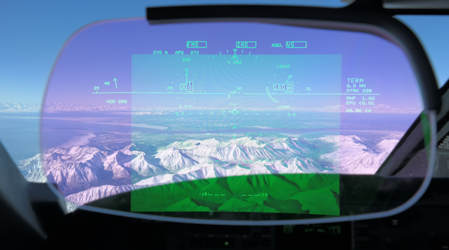
Figure: G450 HUD over Alaska, from Mike Keller
System — First, some hardware.
Symbology — Second, what all those symbols mean.
Caged / Uncaged / Clear — Finally, you need to learn about "caged" and "uncaged."
Takeoff — Then you will be ready for takeoff.
Approach — And your approach and landing.
System
General Description

Figure: HUD Overhead Unit and Combiner, from G450 Aircraft Operating Manual, §2A-34-00, figure 26.
[G450 Aircraft Operating Manual, §2B-18-10]
The HUD displays all necessary flight guidance and navigation data for the pilot on a combiner glass that is mounted in the pilot’s normal field of view out of the forward windscreen. This is done by projecting images from the overhead unit onto the combiner. The system is designed so that the display appears to be towards infinity, allowing the pilot to see the outside world as well as the information on the combiner without changing focus.
The HUD system is designed to function as a supplementary display device that shows the pilot primary flight and navigation information.
The HUD system is designed for use during all phases of flight and allows the pilot to transition from instruments to head-up flying during the critical phase of the takeoff or approach. The conformal nature of the symbols allows symbol guidance to be mixed with the visual cues to increase pilot performance (i.e., during a VFR black hole approach at night to an airport surrounded by unlit terrain).
Combiner Assembly
G450 Aircraft Operating Manual, §2A-34-70, ¶2.A.]
The combiner assembly is mounted above and forward of the pilot on the cockpit overhead at the juncture with the windshield. The assembly contains the HUD display screen and a brightness control. The display incorporates a dielectric coating that acts as a frequency selective filter, reflecting only the color green at high efficiency and bypassing all other light frequencies, thus remaining transparent. The flight guidance cues projected on the screen from the overhead unit take on holographic qualities and appear suspended in space due to the unique qualities of the display coating.
Since the screen position is fixed when extended, the pilot using the display must adjust seat height to align the viewing position with the design eye location of the display. An alignment guide is displayed when the TEST button is depressed on the display controller when in the HUD mode. Two “T” symbols are shown, one on the top of the display in a normal orientation, and another at the bottom of the display in an inverted position. The pilot adjusts seat height while the TEST button is depressed to a position that allows both “T” symbols to be seen. When seat height has been correctly adjusted, the symbology displayed on the combiner screen matches the real world view that it represents - i.e. the artificial horizon overlays the real horizon, etc.
Very few pilots feel comfortable with the seat this far forward but should consider sitting as far forward as they can so as to take full advantage of what the HUD has to offer and to increase their lookdown angle from the cockpit. We used to say in the Boeing 747 that each inch aft of optimal seating position added 500' RVR to a pilot's minimums. Sounds ominous and I have no idea if that was true. But the point is this: the further forward you sit the better the odds you will see a more complete picture of what is in front of the aircraft.
The flight guidance cues shown on the combiner screen are of the same format as any Primary Flight Display (PFD), and arranged in the same layout: a “V” airplane symbol at the horizon in the middle of the screen with heading data at the top, airspeed on the left, altitude on the right and course information below. The cues are displayed in green color, with the screen field of view remaining transparent due to properties of the coating material used on the display glass. The display symbology is active with full mobility within the display range. Cues are stroke written with a rapid refresh rate that eliminates any hesitancy in symbol movement.
Overhead Unit
G450 Aircraft Operating Manual, §2A-34-70, ¶2.B.]
The overhead unit contains an optical module and multiple lens elements that create flight guidance symbology on a Cathode Ray Tube (CRT) in response to graphic input from the Display Drive Unit and project the CRT image onto the combiner screen in a phosphorescent green hue.
During installation of the overhead unit and combiner, a precision alignment process using transits and levels insures that the imagery projected by the overhead unit is correctly focused and positioned to conform to the external environment. After completion of the alignment process, the overhead unit and combiner mount are fixed in place with no further adjustment to the display available, except to remove the units for maintenance.
Declutter Switch
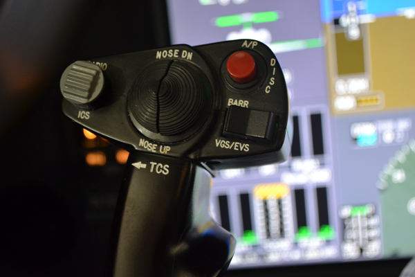
Figure: G450 Declutter Switch, from Eddie's aircraft.
G450 Aircraft Operating Manual, §2A-34-70, ¶2.E.] A declutter switch on the outboard side of the pilot yoke can be used to simplify the graphic information displayed on the combiner screen. Depressing the switch sends a signal to MAU #1 to remove the following visual data if present on the combiner:
Airport and runway symbols
HSI and CDI associated symbols
Altitude dial and pointer, metric altitude and altitude bugs
Airspeed / mach speed dial, pointer and bugs
Navigation source, distance and DME hold annunciation
Selected HDG and CRS digits
Wind display
Preselected altitude
Vertical speed worm
Heading scale and bug
Heading mode annunciation
Max operating annunciation
Brightness Control
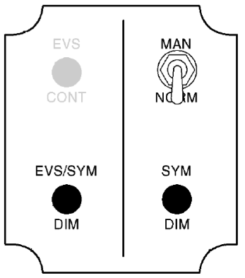
Figure: HUD brightness control panel, MAN/NORM, from G450 Aircraft Operating Manual, §2B-18-10, page 6.
MAN/NORM
[G450 Aircraft Operating Manual, §2B-18-10 ¶3.]
The MAN/NORM switch operates the same as when EVS is not installed. When the switch is in the NORM position, the display brightness is automatically adjusted for ambient light changes.
When the mode switch is in the MAN position, the display brightness can be manually adjusted from zero to full intensity with the system dimming (SYM DIM) (or EVS/SYM DIM) knob. When the switch is in the NORM position, the display brightness is set for ambient light conditions with the SYM DIM (or EVS/SYM DIM) knob and the brightness is automatically adjusted for changes in ambient light conditions. If EVS is installed, the brightness control panel on the combiner assembly has two knobs for controlling the EVS video contrast and brightness.
You can think of the MAN/NORM switch as the switch that enables the two DIM switches. In the NORM position they don't work and you are at the mercy of what the computer thinks you should be seeing. It has been my experience that most pilots don't trust it, since having it decide you need full brightness at the darkest part of an approach could be a big problem. Leaving the switch in MAN gives you control of the bottom two switches.
SYM/DIM

Figure: HUD brightness control panel, SYM DIM, from G450 Aircraft Operating Manual, §2B-18-10, page 6.
[G450 Aircraft Operating Manual, §2B-18-10 ¶3.] SYM DIM Knob — The SYM DIM knob controls the brightness of the HUD symbols. This lets the pilot adjust the brightness level between the symbols and the video.
The SYM DIM switch only controls the brightness of the HUD symbology and can be overwhelmed by the EVS brightness. If you find the switch doesn't seem to work, first make sure the HUD is working and then make sure the EVS isn't overpowering the non-EVS symbology.
The EVS Side
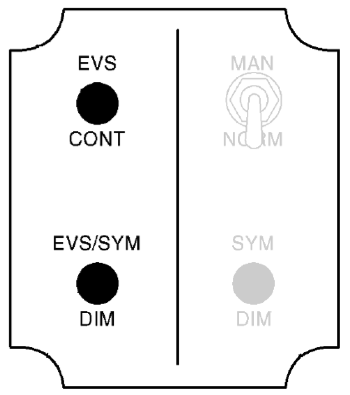
Figure: HUD brightness control panel, from G450 Aircraft Operating Manual, §2B-18-10, page 6.
EVS CONT
[G450 Aircraft Operating Manual, §2B-18-10 ¶3.] The EVS CONT knob controls the contrast of the EVS video that is displayed on the combiner assembly.
[G450 Aircraft Operating Manual, §2A-34-90 ¶.D.] A separate EVS CONT knob, installed above the EVS / SYM DIM knob, is used to set the contrast of the EVS infrared image shown on the combiner screen.
The EVS contrast can do everything from make the imagery disappear to flood the screen with a field of green that makes everything impossible to see.
EVS/SYM DIM
[G450 Aircraft Operating Manual, §2B-18-10 ¶3.] The EVS/SYS DIM knob adjusts the EVS video and HUD symbol brightness.
[G450 Aircraft Operating Manual, §2A-34-90 ¶.D.] In the MAN position the EVS / SYM DIM knob to the left and below the switch is turned to set light levels of the EVS raster image and the HUD flight guidance symbology. With the MAN / NORM switch in NORM, the EVS / SYM DIM knob can set the initial desired illumination level and an automatic brightness sensor on the combiner will subsequently adjust the illumination to compensate for changes in ambient light conditions.
Technique
The HUD Brightness Control Panel can seem a bit mysterious because of the interaction of the four controls and the sometimes recalcitrant nature of the HUD itself. A few pointers:
The EVS CONT button, if missed, can mask other issues so you need to start it from a position of known contrast. Try rotating it counterclockwise until it has no effect on the display, then rotate clockwise six clicks and leave it there.
If there is no HUD display at all after adjusting the EVS CONT button, you should ensure the HUD is working. Try stowing and redeploying the HUD display. If it isn't far enough or too far from the deployed position, it will blank out. Pull up the EVS video page on a DU. It should show HUD symbology with the HUD display deployed. If not, you may need to reboot the airplane.
If you want to trust the MAN/NORM system in NORM, you are done with this panel. If you do not see EVS from the FLIR camera, bring up the EVS on a DU. Remember there are warm up and cool down times to consider.
More about that: G450 Enhanced Vision System.
In the MAN position, you should first adjust the EVS/SYM DIM switch to bring up the lowest level of FLIR imagery to be able to discern the infrared images, and then bring up the SYM DIM so HUD symbology can be seen.
Symbology

Figure: G450 HUD Symbology Overview, from Eddie's notes.
The manuals on the G450 Heads Up Display are poorly written and missing a lot of detail. You can get by without them, I suppose, but the system is capable of much more than just what we absorb through a few days in school and from day-to-day use. I've tried to organize what does appear in print so it makes more sense, adding what we've learned along the way.
Airport Symbol

Figure: G450 HUD Airport Symbol, from Eddie's notes.
[G450 Aircraft Operating Manual, §2B-18-20, ¶2.A., page 33.] The conformal airport symbol is displayed at the end of the runway centerline when the aircraft is on an ILS or MLS approach course and 2000 ft above the airport. The display is the equivalent of an airport 800 feet across. At 2000 feet and a -3° reference FPA, the symbol is at its narrowest and at 1200 feet it widens to show the perspective of the approaching airport. It is at its widest at 325 feet AGL. Accurate placement of the airport symbol requires that FPA is set, lateral deviation is less than two dots, valid vertical deviation is less than three dots, AUTO is selected on the display controller HUD menu page, NAV source is LOC or MLS, altitude is between 325 ft and 2000 ft AGL, and the FPV is below -1° pitch. NOTE: The airport symbol is displayed correctly if the runway elevation has been entered on the display controller HUD menu. If runway elevation has not been entered, the airport display may be displayed too soon or too late, depending on the difference between the actual runway elevation and the default runway elevation that is used by the HUD software.
[G450 Aircraft Operating Manual, §2B-18-10, page 7.] The [Display Driver Unit] computes and displays synthetic airport and runway symbols using glideslope and localizer information, making the lower end of the displayed runway the touchdown zone. The airport symbol is based on an 800-foot wide airport. The runway display is based on a 150-footwide 8000-foot long runway. The pilot must set the runway threshold elevation and glideslope angle using the HUD menu on the DC to ensure accurate symbol placement. Runway heading is determined from the localizer course selected by the pilot.
[G450 Aircraft Operating Manual, §2B-18-10, page 9.] [The display controller] RW ELEV Key is used to set the runway elevation of the destination airport between --1500 and 16,000 feet. This information is used to calculate at what altitude the airport and runway symbols are displayed. If the runway elevation is not properly set, the airport and runway symbols may be incorrect (i.e., without runway elevation).
The airport symbol only appears if you have everything dialed in to fly an ILS or MLS approach and once you descend below 2,000 feet. It doesn't look like an airport, it looks like a fat runway. In fact, it turns into a runway at 350 feet above the runway. That begs the question, how do you tell them apart. Here's how:

Figure: G450 HUD Symbology Airport versus Runway Symbols, from Eddie's notes.
Reading between the lines: the airport symbol uses the localizer or MLS beam for geographical placement, the FMS for perspective, the radio altimeter for vertical placement, and the guidance panel course selection for runway heading. The airport symbol attempts to show you where the runway is, using a larger than the runway perspective, until 325' radio altimeter height, at which point it changes to the runway symbol. The touchdown zone of the runway symbol is determined by the glide slope beam.

Photo: G450 Display Controller HUD Menu - Rwy Elev, from Eddie's aircraft.
The RW ELEV entry in the display controller HUD menu should always be made using QNH altitude, even if the PFD is using QFE. This isn't written anywhere, but we've noticed that if you enter 0' when flying QFE, the airport and runway symbols will appear late by the difference between QFE and QNH.
If, for example, the runway elevation is 100' MSL for a QFE airport you would adjust your PFD altimeter to the proper QFE and it will read 0' on touchdown. If you were to set your display controller HUD RWY ELEV to 0', the airport symbol will appear at 2,000 - 100 = 1900' and the runway symbol will appear at 325' - 100' = 225'. We've tested this and one of these days we'll test an airport greater than 325' MSL to see if the runway symbol fails to appear completely.
Airspeed Dial

Figure: G450 HUD Airspeed Dial, from Eddie's notes.
[G450 Aircraft Operating Manual, §2B-18-20, ¶2.A., page 19.]
The current IAS/Mach is displayed digitally in the center of the analog IAS/Mach dial. The dial consists of 10 unlabeled dots with a dot at the 12 o’clock position that acts as a zero point. Each dot represents 10 knots or 0.01 M, depending on the speed mode selected on the guidance panel. The pointer rotates within the dial and points to the current IAS/Mach.
The airspeed bug is set manually using the guidance panel or automatically through the FMS. The selected airspeed is displayed digitally above the airspeed dial. The bug is displayed on the airspeed dial when the selected airspeed is within 50 knots of actual airspeed.
The secondary airspeed is a digital readout of the current airspeed. If the primary dial is displaying MACH, the secondary dial is IAS. The display is a three-digit readout for IAS and, if selected, the MACH readout is a two-digit value preceded by a zero and a decimal point. If the MACH value is less than 0.40, the digits are removed.
[G450 Aircraft Operating Manual, §2B-18-20, ¶2.A., page 21.] The VSPEEDS are annunciated around the analog airspeed dial and on the speed error tape. When selected and boxed on the DC, the VSPEEDS VR, V1, V2, VFS, VSE, and VRF are indicated with an R, 1, 2, FS, SE, and RF, respectively.
If you have EVS/FLIR turned on, the dial and pointer will disappear and all you will have is the box with the numbers, the selected and secondary speeds. (Nothing in writing says this, but it is so.)
Altitude Awareness Bug

Figure: G450 HUD Altitude Awareness Bug, from Eddie's notes.
[G450 Aircraft Operating Manual, §2B-18-20, ¶2.A., page 17.] The altitude awareness bug displays the difference between the selected altitude and the barometric altitude. It is displayed to the right of the FPV and it moves vertically relative to the horizon line. The bug moves vertically 1° per 100 ft. Half of the bug is displayed when the difference is greater than ±1000 ft. The bug is removed when the difference is less than ±10 feet. However, it is redisplayed when the difference reaches ±100 ft. The bug is not displayed when the FD vertical capture mode shows GS or GP.
Altitude Dial

Figure: G450 HUD Altitude Dial, from Eddie's notes.
[G450 Aircraft Operating Manual, §2B-18-20, ¶2.A., page 16.] The current barometric altitude is digitally displayed in the center of the analog altitude dial. The dial consists of 10 unlabeled dots with one dot at the 12 o’clock position to indicate the zero point. Each dot represents 100 ft barometric altitude, so one full rotation of the dial indicates 1000 ft. The altitude indicator arrow rotates within the dial and indicates current barometric altitude. The selected altitude readout is displayed digitally above the dial.
If you have EVS/FLIR turned on, the dial and pointer will disappear and all you will have is the box with the numbers, and the selected altitude above. (Nothing in writing says this, but it is so.)
Boresight

Figure: G450 HUD Boresight, from Eddie's notes.
[G450 Aircraft Operating Manual, §2B-18-10, ¶2, page 5.] Overhead Unit (OHU). The OHU is located above and slightly behind the pilot’s head. It is mounted in a one-piece tray with the combiner. The tray is boresighted to the aircraft during its initial installation.
[G450 Aircraft Operating Manual, §2B-18-20, ¶2.A., page 12.] The aircraft reference symbol serves as a stationary representation of the longitudinal axis of the aircraft.
The boresight is the nose of the airplane, it never changes. You can think of it as the pointy end of the airplane and the pointy end of the airplane symbol on a conventional attitude indicator. The only time I look at the boresight is when flying a stall recovery, wind shear, or CFIT.
Conformal Lateral Deviation Indicator, Scale, Centerline

Figure: G450 HUD Conformal Lateral Deviation Indicator, from Eddie's notes.
[G450 Aircraft Operating Manual, §2B-18-10, ¶2, page 26.] The [Conformal Lateral Deviation Scale] is described for various navigation sources in [the table below]. The centerline is the indicator of aircraft position along the lateral deviation scale.
DeviationVOR/TACANLOC/MLSFMS 1/2/3FMS 1/2/3 APP
2nd dot right / 10° 2° / 5 NM / Based on RNP
1st dot right / 5°1° / 2.5 NM / Based on RNP
Center / 0°0° / 0 NM / Based on RNP
1st dot left / 5°1° / 2.5 NM / Based on RNP
2nd dot left / 10°2° / 5 NM / Based on RNP
To see a conformal lateral deviation display like this, you need to select LSK 5L AUTO from the display controller HUD menu. Once you are within 12° of course the HSI or CDI displayed (depending on LSK 4L) will switch to the conformal display.
[G450 Aircraft Operating Manual, §2B-18-10, ¶6, page 9.] Pushing [the LSK 5L] key scrolls through AUTO, ON, and OFF. This key selects the lateral display format from one of the following HUD displays:
HSI
CDI
Conformal lateral deviation
Non-conformal deviation.
AUTO -- Selects one of three positions, and the effect of the selected position depends on whether the CDI or the HSI is selected. [The table below] describes this key selection relative to the selected display.
ON -- Selects full HSI or CDI display format depending on what was selected on LSK 4L.
OFF -- Results in a non-conformal CDI display only.
Course Select/Desired Track Error < 12°: Course Select/Desired Track Error > 12°:
AUTO Conformal only Full HSI or CDI (Note 1)
ON Full HSI or CDI (Note 1) Full HSI or CDI (Note 1)
OFF Non-conformal CDI only Non-conformal CDI only
NOTES:
1. Depends on the selection made with the HSI/CDI line select key.
2. For a typical ILS approach, select AUTO and CDI. As the localizer moves to less than 12°, the display automatically switches to the conformal CDI display if it was not previously selected.
3. The power-up setting is the combination set when the aircraft was last powered-down.
[G450 Aircraft Operating Manual, §2B-18-10, ¶6, page 8.] When the AUTO has been selected ON, pushing the CDI/HSI key toggles HUD display between the CDI display and the HSI display format.
Course Deviation Indicator, Scale, To/From

Figure: G450 HUD CDI, from Eddie's notes.
[G450 Aircraft Operating Manual, §2B-18-10, ¶2, page 23.] The scale consists of four dots (two dots of deviation to the left and two to the right centered about the FPV). The deviation pointer indicates the amount of deviation from the selected NAV source. The arrow on the pointer indicates the selected course. The CDI rotates around the FPV based on the course selected using the CRS select knob on the guidance panel. TO is indicated by a circle near the arrow’s point. FROM is indicated by a circle near the arrow’s tail.
If you want to see a CDI like this at all times, you need to select LSK 5L ON and LSK 4L CDI from the display controller HUD menu. If you select LSK 5L AUTO and LSK 4L CDI, you will get the CDI display until you get within 12° of course, at which time you will get the conformal display.
[G450 Aircraft Operating Manual, §2B-18-10, ¶6, page 9.] Pushing [the LSK 5L] key scrolls through AUTO, ON, and OFF. This key selects the lateral display format from one of the following HUD displays:
HSI
CDI
Conformal lateral deviation
Non-conformal deviation.
AUTO -- Selects one of three positions, and the effect of the selected position depends on whether the CDI or the HSI is selected. [The table below] describes this key selection relative to the selected display.
ON -- Selects full HSI or CDI display format depending on what was selected on LSK 4L.
OFF -- Results in a non-conformal CDI display only.
Course Select/Desired Track Error < 12°. Course Select/Desired Track Error > 12°
AUTO Conformal only Full HSI or CDI (Note 1)
ON Full HSI or CDI (Note 1) Full HSI or CDI (Note 1)
OFF Non-conformal CDI only Non-conformal CDI only
NOTES:
1. Depends on the selection made with the HSI/CDI line select key.
2. For a typical ILS approach, select AUTO and CDI. As the localizer moves to less than 12°, the display automatically switches to the conformal CDI display if it was not previously selected.
3. The power-up setting is the combination set when the aircraft was last powered-down.
[G450 Aircraft Operating Manual, §2B-18-10, ¶6, page 8.] When the AUTO has been selected ON, pushing the CDI/HSI key toggles HUD display between the CDI display and the HSI display format.
Flare Cue

Figure: G450 HUD Flare Cue, from Eddie's notes.
[G450 Aircraft Operating Manual, §2B-18-10, ¶5., page 7.] The radio altitude is used to calculate runway symbol and flare cue placement.
[G450 Aircraft Operating Manual, §2B-18-20, ¶2.A., page 35.] The flare cue is armed, but not displayed, when the aircraft is airborne, and RA is +400 ft for 5 seconds. Once armed, when the radio altimeter (RA) is <100 ft AGL, the flare cue is displayed. When the flare cue is activated, it moves up from below the FPV. As the aircraft descends to 50 feet RA, the flare cue rises to surround the FPV. When the aircraft descends below 50 ft AGL, the cue switches from glideslope to the FD vertical command. The FD vertical command also drives the flare cue below 50 ft. If the pilot maintains the wings of the FPV between the parallel lines of the flare cue and pulls power to idle, the aircraft flares to a landing. Touchdown and roll out are performed using normal visual procedures.
The book doesn't explain which "FD vertical command" is used to flare the aircraft but it appears to be level flight at 0' feet, which means it doesn't land the airplane properly. The key phrase here is "using normal visual procedures."

Photo: HUD FPA in flare, KPSM, from Eddie's HUD.
We have found that following the flare cue until touchdown usually leads to a long landing.
See Landing for a better way to do this.
Video: KBED - KPSM with HUD.
Flight Director

Figure: G450 HUD Flight Director, from Eddie's notes.
[G450 Aircraft Operating Manual, §2B-18-20, ¶2.A., page 8.]
The FD command symbol moves laterally and vertically for guidance. To capture the FD guidance, the pilot maneuvers the aircraft to place the FPV over the FD, both vertically and laterally. If a single cue flight director is selected on the DC, the diamond is displayed with wings and the symbol rolls and moves sideways to indicate lateral commands. When the cross-pointer flight director is selected on the DC, the diamond is displayed with out wings and it does not roll. In both cases, the FD is satisfied by centering the FPV over the FD.
FD modes come from the priority AFCS, and autothrottle modes come from the priority performance computer. Both armed and captured modes are displayed, with captured modes being displayed inside a box. When a mode is captured, a box is drawn around it, and it flashes for 5 seconds and then goes on steady. If an unusual attitude exists, the modes are removed from the display and FD FAIL is displayed. Flight director modes are described in [the table below].
Lateral Modes
Lateral Mode Annunciator
Heading select HDG
LNAV FMS FMS
LNAV VOR VOR
Approach VOR VORAP
LNAV NMS. NMS
Approach ILS LOC
Back Course. BC
Emergency Descent EDM
Overstation OS
TACAN TCN
Approach TACAN TCNAP
Autothrottle Modes
Autothrottle Mode Annunciator
Takeoff TO
Go Around GA
Flight Level Change. FLCH
Speed IAS. IAS
Speed Mach MACH
Retard RTD
Hold Mode HOLD
Override OVRD
VMO Limited. VMO
MMO Limited. MMO
Power Limited POWER
Flap Limited FLAPS
Gear Limited GEAR
VMIN Limited VMIN
Vertical Modes
Vertical Mode Annunciator
Altitude Hold ALT
Vertical Speed. VS
Altitude Select. ASEL
FLCH IAS IAS
FLCH MACH MACH
Approach ILS GS
Approach MLS. GP
Takeoff TO
Go Around. GA
VNAV ALT Preselect VASEL
VNAV ALT Hold VALT
VNAV FLCH IAS VIAS
VNAV FLCH MACH VMACH
VNAV ARM VNAV
VNAV Path VPATH
Flight Path Angle FPA
VMAX VMAX
Flight Path Vector
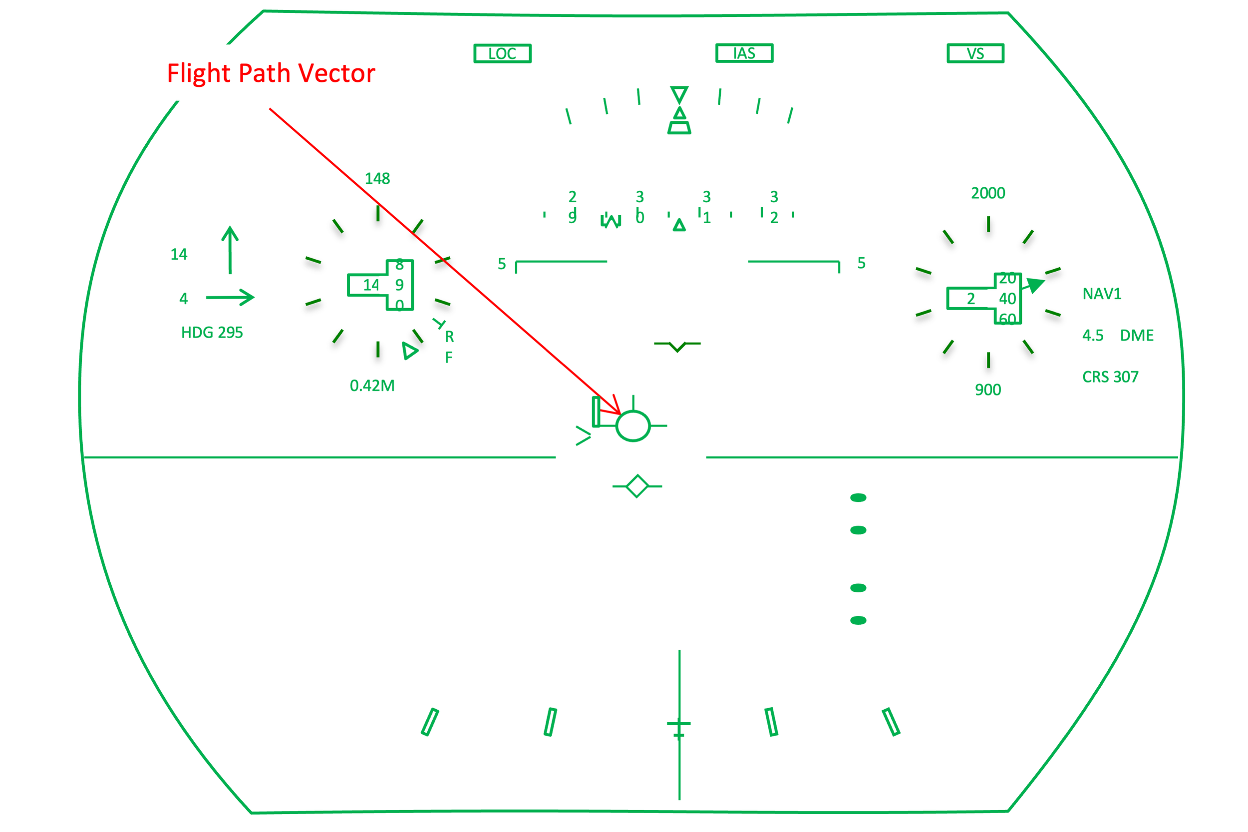
Figure: G450 HUD Flight Path Vector, from Eddie's notes.
[G450 Aircraft Operating Manual, §2B-18-20, ¶2.A., page 14.] The FPV is the primary symbol for control of the aircraft. The FPV displays the current velocity vector of the aircraft. The lateral displacement vector is calculated from the selected IRS drift angle and the vertical vector is calculated from the IRS flight path angle. Inputs from the GPS system (if installed) are used to improve the accuracy of the IRS data. The FPV does not display nose attitude as does the normal attitude indicator. If the aircraft is descending, the FPV is displayed below the HUD horizon at the current flight path angle of the aircraft. If the aircraft is climbing, the symbol is above the horizon line at the current flight path angle. Displacement of the FPV laterally indicates drift. Full-scale deflection indicates 12° of drift. The lateral and vertical motion of the symbol are restricted to ±12° in the uncaged mode, and 0° laterally in the caged mode. The FPV flashes when it is at its limit. The FPV becomes active when the IAS is 63 knots or greater, disabled when IAS is 60 knots or less.
The IRU drives the flight path vector, telling it how high above the local horizon to be based on the aircraft's vertical motion and how far right or left of center based on drift angle.
The flight path vector is my favorite bit of technology on the airplane and I use it for all my instrument flying needs. In fact, the only time I ignore it and revert to the the old fashioned boresight is for stall recoveries, wind shear escape maneuvers, and CFIT avoidance. In these cases the flight path vector is jumping around too erratically to follow.

Figure: Angles of Attack and Incidence
You can think of the bore sight as being attached to the nose of the airplane and the flight path vector as where the aircraft is heading. While instructors are fond of saying the gap between the bore sight and the flight path vector is the angle of attack, this isn’t true. The angle of attack is the gap between the flight path vector and the chord line of the wing. I don’t know of any aircraft that show you the chord line on your flight displays. Just as a reminder, the angle between the chord line of the wing and the bore sight is the angle of incidence. In plain language, on most aircraft the wing is mounted with an angle up from the fuselage. That is the angle of incidence.
There are times you can see the bore sight below the flight path vector, though it is rare:
Prior to takeoff rotation.
After landing touchdown,
During an aggressive climb where the aircraft’s thrust allows the nose to come up while holding speed, even if briefly. I’ve seen this a few times in the G500 but not in the G450.
More about this: Angle of Attack.
Ghost Flight Path Vector
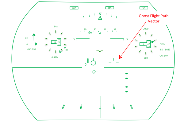
Figure: G450 HUD Ghost Flight Path Vector, from Eddie's notes.
[G450 Aircraft Operating Manual, §2B-18-20, ¶2.A., page 14.] The ghost FPV is displayed when the caged mode is selected on the DC HUD menu, and the drift angle (the difference between the actual velocity vector and the caged FPV) is 1.5° or greater. The ghost FPV is used during high crosswind conditions. This means the pilot can observe the actual flight path while the FPV symbol and associated symbols are caged to the center of the display. The ghost FPV flashes and remains in view when it reaches the lateral limits of the display.
When the flight path vector is uncaged, it points to where the aircraft is headed up to the limits of the viewing angle on the HUD and then it flashes to let you know it would actually be further left or right if it could. Even at these limited extremes it can be difficult to see so you have the option of caging the flight path vector to the center of the HUD. In this case, the ghost flight path vector shows you where the aircraft is actually headed, again up to the limits of the viewing angle of the HUD.
Heading Bug

Figure: G450 HUD Heading Bug, from Eddie's notes.
[G450 Aircraft Operating Manual, §2B-18-20, ¶2.A., page 16] The heading select bug indicates the heading that was selected using the HDG SEL knob on the guidance panel. When the selected heading is off the displayed heading scale, the bug is displayed as a half-bug parked on the side of the heading scale closest to the selected heading. The digital readout indicates the numerical value (in degrees) of the heading select bug. The readout consists of three digits preceded by the HDG annunciator.
Heading Tape

Figure: G450 HUD Heading Tape, from Eddie's notes.
[G450 Aircraft Operating Manual, §2B-18-20, ¶2.A., page 15.] The heading tape is a 40° non-conformal scale that moves horizontally left and right. The scale has labeled tick marks every 10°, with shorter tick marks every 5°. Heading readouts are two-digit numbers that leave off the least significant digit (i.e., 30 equals 300°). The scale indicates in magnetic unless the true mode is selected on the FMS. When true heading is selected, a TRU annunciator is displayed above the selected heading. In the CLEAR mode, the scale is replaced with a three-digit indication of actual heading.
Horizontal Situation Indicator

Figure: G450 HUD HSI, from Eddie's notes.
[G450 Aircraft Operating Manual, §2B-18-10, ¶2, page 24.] The standard HSI display is selected using the DC HUD menu. The arrow points to the selected course. The TO/FROM indicator is a triangle that is attached to the head (TO) or tail (FROM) of the arrow. The lateral deviation scale is centered on the aircraft symbol with the deviation bar indicating course deviation. The selected heading is displayed as a bug on the outside of the heading dial.
If you want to see an HSI like this at all times, you need to select LSK 5L ON and LSK 4L HSI from the display controller HUD menu. If you select LSK 5L AUTO and LSK 4L HSI, you will get the HSI display until you get within 12° of course, at which time you will get the conformal display.
The HSI display is only available with the EVS/FLIR turned off. (Nothing says this, but that has been our experience in actual practice.)
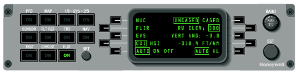
Figure: G450 Display Controller HUD Page, from Eddie's notes.
[G450 Aircraft Operating Manual, §2B-18-10, ¶6, page 9.] Pushing [the LSK 5L] key scrolls through AUTO, ON, and OFF. This key selects the lateral display format from one of the following HUD displays:
HSI
CDI
Conformal lateral deviation
Non-conformal deviation.
AUTO -- Selects one of three positions, and the effect of the selected position depends on whether the CDI or the HSI is selected. [The table below] describes this key selection relative to the selected display.
ON -- Selects full HSI or CDI display format depending on what was selected on LSK 4L.
OFF -- Results in a non-conformal CDI display only.
Course Select/Desired Track Error < 12°. Course Select/Desired Track Error > 12°
AUTOConformal only Full HSI or CDI (Note 1)
ON Full HSI or CDI (Note 1) Full HSI or CDI (Note 1)
OFF Non-conformal CDI only Non-conformal CDI only
NOTES:
1. Depends on the selection made with the HSI/CDI line select key.
2. For a typical ILS approach, select AUTO and CDI. As the localizer
moves to less than 12°, the display automatically switches to the
conformal CDI display if it was not previously selected.
3. The power-up setting is the combination set when the aircraft was
last powered-down.
[G450 Aircraft Operating Manual, §2B-18-10, ¶6, page 8.] When the AUTO has been selected ON, pushing the CDI/HSI key toggles HUD display between the CDI display and the HSI display format.
Instantaneous Acceleration Caret

Figure: G450 HUD Instantaneous Acceleration Caret and Speed Error Tape, from Eddie's notes.
[G450 Aircraft Operating Manual, §2B-18-20, ¶2.A., page 22.] The caret indicates current acceleration/deceleration of the aircraft along the current flight path. With its zero position at the end of the FPV left wing, it indicates above the wing when airspeed is increasing, and below the wing when airspeed is decreasing. The caret is primarily used to control airspeed. It is also scaled so that its position gives an indication of the aircraft flight path angle so that, if flown, current airspeed would be maintained at the current power setting.
Using the speed error tape in conjunction with the instantaneous acceleration caret gives you a wealth of information on the aircraft's energy state:

Figure: G450 HUD Speed Cues, from Eddie's notes.
Local Horizon

Figure: G450 HUD Local Horizon, from Eddie's notes.
[G450 Aircraft Operating Manual, §2B-18-20, ¶2.A., page 12.] The horizon line is drawn across the HUD display with a gap in the center to allow room for the FPV to move vertically. The horizon line is held on-screen and flashes if the pitch-up exceeds 13° or the pitch-down exceeds 6°. The horizon line is displayed at 0° angle of pitch on the pitch tape. NOTE: The horizon line indicates the aircraft’s local horizon. At high altitudes, the line appears above the visual horizon line because of the curvature of the earth.
Non-conformal Lateral Deviation Indicator, Scale, To/From

Figure: G450 HUD Non-conformal Lateral Deviation Indicator, from Eddie's notes.

Figure: G450 HUD Non-conformal Lateral Deviation Indicator, from Eddie's notes.
[G450 Aircraft Operating Manual, §2B-18-10, ¶2, page 25-26.] The non-conformal deviation scale is centered on the aircraft boresight and below the FPV symbol. It is displayed 3.5° below the reference FPA, if the selected NAV 1/2 and the selected NAV source are tuned-to-localizer, or if it is MLS. The deviation scale is displayed 6° below the horizon line if the selected NAV source is VOR, NAV 1/2, or FMS. It is displayed only when the display controller HSI/CDI mode is selected OFF or the conformal display moves off the bottom of the display (typically, during a go-around). The deviation pointer indicates as described in [the table below]. The TO indicator is displayed above the aircraft symbol, and the FROM indicator is displayed below it.
Deviation VOR/TACAN LOC/MLS FMS 1/2/3 FMS 1/2/3 APP
2nd dot right 10° 2° 5 NM Based on RNP
1st dot right 5° 1° 2.5 N M Based on RNP
Center 0° 0° 0 NM Based on RNP
1st dot left 5° 1° 2.5 NM Based on RNP
2nd dot left 10° 2° 5 NM Based on RNP
If you want to see a non-conformal lateral deviation display like this at all times, you need to select LSK 5L OFF from the display controller HUD menu. You could also see this if you were in AUTO and pitched high enough to make the conformal scale disappear from view.

Figure: G450 Display Controller HUD Page, from Eddie's notes.
[G450 Aircraft Operating Manual, §2B-18-10, ¶6, page 9.] Pushing [the LSK 5L] key scrolls through AUTO, ON, and OFF. This key selects the lateral display format from one of the following HUD displays:
HSI
CDI
Conformal lateral deviation
Non-conformal deviation.
AUTO -- Selects one of three positions, and the effect of the selected position depends on whether the CDI or the HSI is selected. [The table below] describes this key selection relative to the selected display.
ON -- Selects full HSI or CDI display format depending on what was selected on LSK 4L.
OFF -- Results in a non-conformal CDI display only.
Course Select/Desired Track Error < 12° Course Select/Desired Track Error > 12°
AUTO Conformal only Full HSI or CDI (Note 1)
ON Full HSI or CDI (Note 1) Full HSI or CDI (Note 1)
OFF Non-conformal CDI only Non-conformal CDI only
NOTES:
1. Depends on the selection made with the HSI/CDI line select key.
2. For a typical ILS approach, select AUTO and CDI. As the localizer moves to less than 12°, the display automatically switches to the conformal CDI display if it was not previously selected.
3. The power-up setting is the combination set when the aircraft was last powered-down.
[G450 Aircraft Operating Manual, §2B-18-10, ¶6, page 8.] When the AUTO has been selected ON, pushing the CDI/HSI key toggles HUD display between the CDI display and the HSI display format.
Pitch Limit Indicator (PLI)

Figure: G450 HUD PLI, from Eddie's notes.
[G450 Aircraft Operating Manual, §2B-18-20, ¶2.A., page 13.] The PLI is displayed when the normalized AOA is greater than 0.7 and is used as a visual cue to alert the pilot to an impending stick shaker. As the FPV approaches the PLI, the pilot is approaching stick shaker activation. The distance between the PLI and FPV is zero when the stick shaker is activated.
Pitch Tape

Figure: G450 HUD Pitch Tape, from Eddie's notes.
[G450 Aircraft Operating Manual, §2B-18-20, ¶2.A., page 12.] The pitch tape displays the conformal attitude at all times. The tape has solid reference marks for positive pitch and dashed reference marks for negative pitch. The pitch tape moves as earth referenced over a range of ±90° pitch and ±180° roll. The -5° pitch reference is removed when the reference FPA is displayed below the horizon line.
Reference Flight Path Angle

Figure: G450 HUD Reference Flight Path Angle, from Eddie's notes.
[G450 Aircraft Operating Manual, §2B-18-20, ¶2.A., page 32.] The reference FPA line is a dashed line that is positioned above or below the horizon line to display the selected FPA. The gap in the line is centered and moves laterally with the FPV. The FPA line is always parallel to the horizon line. The FPA is limited to ±9°. FPA can be selected on the display controller HUD menu page or on the guidance panel. If a reference FPA is seen on both the display controller HUD menu and the guidance panel, the priority is the display controller value. The FPA (vertical angle) is selected on the display controller when the value is boxed. To set the reference FPA on the guidance panel, first select FPA (boxed) on the display controller DISP menu, then set the FPA angle on the guidance panel. The FPA value from the guidance panel is used by HUD if the vertical angle on the display controller HUD menu page is not boxed.
[G450 Aircraft Operating Manual, §2B-18-10, page 9.] [The display controller] VERT ANG Key is used to set the position of the reference flight path angle symbol on the HUD. The maximum allowable range is +9.9° to -9.9°. The corresponding FT/NM is displayed below the vertical angle.
Runway Symbol

Figure: G450 HUD Runway Symbol, from Eddie's notes.
[G450 Aircraft Operating Manual, §2B-18-20, page 34.] The runway symbol is displayed on an ILS or MLS approach when the aircraft is less than 350 feet above the runway and it remains displayed until 60 feet on the RA. The runway symbol represents a runway width of 150 ft with two indentations at the touchdown point, which is assumed to be 1000 ft from the runway threshold. The runway symbol requires that FPA is set, lateral deviation is valid and less than two dots, and vertical deviation is valid and less than two dots. NOTE: The runway symbol is displayed correctly during an ILS or MLS approach if the runway elevation has been entered on the display controller HUD menu and the AUTO mode has been selected. If runway elevation has not been entered, the runway display may be displayed too soon or too late, depending on the difference between the actual runway elevation and the default runway elevation that is used by the HUD software.
[G450 Aircraft Operating Manual, §2B-18-10, ¶5., page 7.] The radio altitude is used to calculate runway symbol and flare cue placement.
[G450 Aircraft Operating Manual, §2B-18-10, page 9.] [The display controller] RW ELEV Key is used to set the runway elevation of the destination airport between -1500 and 16,000 feet. This information is used to calculate at what altitude the airport and runway symbols are displayed. If the runway elevation is not properly set, the airport and runway symbols may be incorrect (i.e., without runway elevation).
[G450 Aircraft Operating Manual, §2B-18-10, page 7.] The [Display Driver Unit] computes and displays synthetic airport and runway symbols using glideslope and localizer information, making the lower end of the displayed runway the touchdown zone. The airport symbol is based on an 800-foot wide airport. The runway display is based on a 150-footwide 8000-foot long runway. The pilot must set the runway threshold elevation and glideslope angle using the HUD menu on the DC to ensure accurate symbol placement. Runway heading is determined from the localizer course selected by the pilot.
[G450 Aircraft Operating Manual, §2B-18-10, page 9.] [The display controller] RW ELEV Key is used to set the runway elevation of the destination airport between --1500 and 16,000 feet. This information is used to calculate at what altitude the airport and runway symbols are displayed. If the runway elevation is not properly set, the airport and runway symbols may be incorrect (i.e., without runway elevation).
The airport symbol only appears if you have everything dialed in to fly an ILS or MLS approach and once you descend below 2,000 feet. It doesn't look like an airport, it looks like a fat runway. In fact, it turns into a runway at 350 feet above the runway. That begs the question, how do you tell them apart. Here's how:

Figure: G450 HUD Symbology Airport versus Runway Symbols, from Eddie's notes.
Reading between the lines: the airport symbol uses the localizer or MLS beam for geographical placement, the FMS for perspective, the radio altimeter for vertical placement, and the guidance panel course selection for runway heading. The airport symbol attempts to show you where the runway is, using a larger than the runway perspective, until 325' radio altimeter height, at which point it changes to the runway symbol. The touchdown zone of the runway symbol is determined by the glide slope beam.

Photo: G450 Display Controller HUD Menu - Rwy Elev, from Eddie's aircraft.
The RW ELEV entry in the display controller HUD menu should always be made using QNH altitude, even if the PFD is using QFE. This isn't written anywhere, but we've noticed that if you enter 0' when flying QFE, the airport and runway symbols will appear late by the difference between QFE and QNH.
If, for example, the runway elevation is 100' MSL for a QFE airport you would adjust your PFD altimeter to the proper QFE and it will read 0' on touchdown. If you were to set your display controller HUD RWY ELEV to 0', the airport symbol will appear at 2,000 - 100 = 1900' and the runway symbol will appear at 325' - 100' = 225'. We've tested this and one of these days we'll test an airport greater than 325' MSL to see if the runway symbol fails to appear completely.
Selected Altitude

Figure: G450 HUD Selected Altitude, from Eddie's notes.
[G450 Aircraft Operating Manual, §2B-18-20, ¶2.A.] The selected altitude bug travels around the outside of the altitude analog scale. The selected altitude range is -2000 to 65,000 ft barometric altitude. The bug is displayed when the aircraft is within ± 500 feet from the selected altitude. The bug is not displayed when the FD vertical capture mode shows GS or GP. The digital readout is the digital value of the bug position. This display can be in metric or English values.
Speed Error Tape

Figure: G450 HUD Instantaneous Acceleration Caret and Speed Error Tape, from Eddie's notes.
[G450 Aircraft Operating Manual, §2B-18-20, ¶2.A., page 21.]
This tape rises or descends from the left wing of the FPV. It represents the difference between the selected airspeed and the current airspeed. If the tape is below the wing, current airspeed is less than the selected airspeed. If the current airspeed is greater than the selected airspeed, the tape is above the wing. The tape is designed so that if the speed error tape is not displayed, the selected airspeed is being maintained.
If V1, VR, or V2 are within the range of the speed error tape, they are displayed to the left of the speed error tape. The indicator moves vertically along the speed error tape, so that the distance between the FPV wing and the VSPEED indicator is proportional to the speed error tape scale. The V1 and VR values are parked at the bottom of the speed error tape if their values place them outside the displayed values on the tape.
Using the speed error tape in conjunction with the instantaneous acceleration caret gives you a wealth of information on the aircraft's energy state:

Figure: G450 HUD Speed Cues, from Eddie's notes.
Vertical Deviation

Figure: G450 HUD Vertical Deviation, from Eddie's notes.
[G450 Aircraft Operating Manual, §2B-18-20, ¶2.A., page 27.] The vertical deviation scale displays either VPATH or glideslope deviation. The scale moves laterally with the FPV. The deviation scale uses the FPA line as its center point when the selected NAV source is NAV 1/2 and it is tuned-to-localizer, or if it is MLS. The pointer moves up and down the scale with a sensitivity of 0.35°/dot for glideslope deviation. If the NAV source is FMS 1/2/3, the pointer is driven by the selected FMS vertical deviation, and the deviation scale center point is at -3°.
Vertical Speed

Figure: G450 HUD Vertical Speed, from Eddie's notes.
[G450 Aircraft Operating Manual, §2B-18-20, ¶2.A., page 18.] The vertical speed digital readout is the vertical speed in terms of feet per minute (FPM). The vertical speed worm indicates the vertical speed. The worm is an arc that originates from the 9 o’clock position of the altitude dial and moves clockwise (cw) for positive vertical speed and counterclockwise (ccw) for negative vertical speed. The scaling is 1000 ft/min per mark for the first 54° of arc, 2000 ft/min per mark for the next 36°, and 3000 ft/min per mark for the next 36°.
Wind Vector

Figure: G450 HUD Wind Vector, from Eddie's notes.
[G450 Aircraft Operating Manual, §2B-18-20, ¶2.A.] The wind vector can be displayed in either the X-Y or vector format, as selected on the DC. Wind data comes from the selected IRS. NOTE: The wind display is the standard wind vector format selection on the DC. It is not a HUD-specific selection. However, this is a non-filtered instantaneous wind vector and it can vary slightly from the ND and MCDU wind values.
Caged / Uncaged / Clear

Figure: ILS approach with wind, from G450 Aircraft Operating Manual, §2B-18-00, figure 1
If you put me and another pilot in a room and ask for opinions on caged versus uncaged, you will get three answers. That's because I have two:
You can operate in either mode but you should be consistent. You need to train your eyes where to look for the information you need in a timely manner, including the runway just as it is coming up on EVS or just plain visually.
If you insist on operating caged for high crosswinds and uncaged for all other times, you might consider just putting the HUD away for high crosswinds since the runway may actually be off the HUD entirely under these conditions.
No matter how you operate, you should know that when the drift angle exceeds 12°, the airplane is headed further left or right than either the flight path vector or the ghost vector are telling you.
HUD Display Mode: Uncaged

Figure: HUD Display Uncaged Mode, from Eddie's note.
[G450 Aircraft Operating Manual, §2B-18-20, ¶4.A., page 46.] In the uncaged mode, the FPV can move up to ±12° laterally and vertically within the display.
The big advantage to the uncaged mode is that your eyes will always be directed to where the airplane is headed. During an approach to a runway with a large crosswind, however, the flight path vector will reach its limit and you must remember to look still further.
HUD Display Mode: Caged

Figure: HUD Display Caged Mode, from Eddie's note.
[G450 Aircraft Operating Manual, §2B-18-20, ¶4.B., page 46.] In the caged mode, the FPV is locked into the center of the display and only vertical movement is allowed. No horizontal movement (i.e., drift angle) is displayed. This keeps the display in an easily readable and flyable position during high crosswinds that could result in an uncaged FPV being displayed at the extreme left or right of the display. If the FPV is caged, and the actual velocity vector position differs laterally by 1.5° or more from the caged position, the ghost FPV is displayed in the actual velocity vector location and shows drift angle as well as climb and descent angles. The ghost FPV is also limited to ±12° laterally and vertically. It flashes when it has reached its limit.
The advantage to the caged mode is that everything is where you expect it to be, all the time. Everything, that is, except the runway.
HUD Display Mode: Clear
Figure: HUD Display Clear Mode, from Eddie's note.
[G450 Aircraft Operating Manual, §2B-18-20, ¶4.C., page 46.] The clear mode removes many of the displayed symbols to give the pilot better visibility. Airspeed, altitude, heading, radio altitude, FPV, and FD, as well as other necessary symbols, are not removed. The clear mode is activated and deactivated by pushing and releasing the touch control steering (TCS) button on the pilot’s yoke. Pushing and releasing the TCS button toggles the display between the normal and clear modes. The operation of the TCS function has not been changed. It activates any time the TCS button is pushed.
This is a good way to get ready for landing after you have disconnected the autopilot. If you press TCS with the autopilot engaged you will have to hand fly for the duration.
Display Controller Menu

Figure: G450 Display Controller HUD Menu Uncaged, from Eddie's aircraft.
[G450 Aircraft Operating Manual, §2B-18-10, ¶6, page 8.] Pushing this key toggles the HUD display between the caged and uncaged modes. The caged and uncaged modes determine how the FPV moves within the display. In the uncaged mode, the FPV can move up to ±12° laterally and vertically within the display. In the caged mode, FPV movement is restricted to vertical motion only and a ghost FPV is also displayed.
Flight Path Vector (Caged or Uncaged)

Figure: G450 HUD Flight Path Vector, from Eddie's notes.
[G450 Aircraft Operating Manual, §2B-18-20, ¶2.A., page 14.] Displacement of the FPV laterally indicates drift. Full-scale deflection indicates 12° of drift. The lateral and vertical motion of the symbol are restricted to ±12° in the uncaged mode, and 0° laterally in the caged mode. The FPV flashes when it is at its limit. The FPV becomes active when the IAS is 63 knots or greater, disabled when IAS is 60 knots or less.
Ghost Flight Path Vector

Figure: G450 HUD Ghost Flight Path Vector, from Eddie's notes.
[G450 Aircraft Operating Manual, §2B-18-20, ¶2.A., page 14.] The ghost FPV is displayed when the caged mode is selected on the DC HUD menu, and the drift angle (the difference between the actual velocity vector and the caged FPV) is 1.5° or greater. The ghost FPV is used during high crosswind conditions. This means the pilot can observe the actual flight path while the FPV symbol and associated symbols are caged to the center of the display. The ghost FPV flashes and remains in view when it reaches the lateral limits of the display.
When the flight path vector is uncaged, it points to where the aircraft is headed up to the limits of the viewing angle on the HUD and then it flashes to let you know it would actually be further left or right if it could. Even at these limited extremes it can be difficult to see so you have the option of caging the flight path vector to the center of the HUD. In this case, the ghost flight path vector shows you where the aircraft is actually headed, again up to the limits of the viewing angle of the HUD.
Takeoff

Figure: G450 EVS Takeoff Presentation, from Eddie's aircraft.
It is easy to ignore the HUD on takeoff, in fact that is how we start our HUD existence, ignoring it and slowly learning how to use it to our advantage. Perhaps we can bypass the ignoring stage with a few pointers.
The photo above, as it says, is from the EVS but the display is the same. We tend to focus on the flight path vector and the flight director diamond, but what do we usually worry about during a takeoff without a HUD? Yup, you should add that speed error tape to your crosscheck.
If you are new to this, you might want to watch this short one-minute video showing a takeoff using the EVS: EVS vs. Visual (Takeoff). (Keep an eye on that speed error tape.)
Set Up

Figure: G450 HUD takeoff set up, from Eddie's notes.
Just as with the PFD, setting the guidance panel with HDG, the heading bug on runway heading, and selecting TO/GA will get you the HDG, TO, TO on the top row of the HUD display. The airspeed should be at the 40 KCAS peg with V2 bugged and indicated above the speed dial.
Unlike the conventional PFD:
The local horizon on the HUD will appear to be at the end of the runway. The PFD has a horizon line of sorts that will be below this.
The flight path vector will be right on the local horizon, since that is where the aircraft is headed prior to rotation. The PFD display will be well below this.
The boresight will be below the local horizon. The PFD aircraft reference symbol points to the same position.
The flight director diamond will be slightly above the local horizon. The PFD will be much higher.
The speed error tape should be rather long off the left wing of the flight path vector and there should be three tick marks in the correct order: V1, VR, and V2. The instantaneous speed carat will be at the wing tip when stationary and should immediately jump up as the aircraft accelerates.
The bottom of the display will have a conventional CDI until you get within 12° of the runway centerline, at which point it becomes conformal.
More about this below: Conformal Lateral Deviation Indicator, Scale, Centerline.
60 KCAS

Figure: G450 HUD takeoff 60 KCAS, from Eddie's notes.
As you accelerate, the speed error tape gets shorter. At 60 KCAS the vertical mode indicator — the second item on the top line of the display — should change from TO to HOLD, which flashes for five seconds before boxing.
As long as the Display Controller HUD menu is set for the CDI in the AUTO mode, you should have a conformal CDI on the bottom of the display. (When you are within 12° of the course, the CDI/HSI selection does not matter when in AUTO.) The book says the CDI will be based on RNP at this point, which is more than likely 1.0 nm. As you can see from the photo on the top of this page, this does not appear to be true.
More about this below: Conformal Lateral Deviation Indicator, Scale, Centerline.
Rotation

Figure: G450 HUD rotation, from Eddie's notes.
As you rotate the boresight will go from below the local horizon and pass to above the flight path vector where it should remain for the rest of the flight until after landing touchdown. You will likely out climb the local horizon which may disappear off the bottom of the display. You will attempt to bring the flight path vector over the flight director diamond. Depending on altitude of the initial level off altitude, you may immediately get an ASEL indication next to the autothrottle flight director annunciator.
Unless you have selected CAGED mode, the flight path vector will probably move left or right away from the relative wind.
Initial Climb
As you continue your initial climb:
The speed error tape will change several times, as a result of flap selection and performance computer inputs.
If your lateral deviation indicator is selected to AUTO, the conformal CDI may change to non-conformal and back, each time you deviate from within 12° of course.
The local horizon will reappear as your climb performance decreases.
When you level off, the flight path vector should end up right on the local horizon.
Approach

Photo: Three views of the same approach at 190 feet, from Eddie's aircraft.
The Heads Up Display puts your eyes where they need to be for an approach in low visibility: on the runway. It is a definite plus. The infrared camera (FLIR)? Not so much. Sometimes it works, sometimes it doesn't. The photo above was one of those rare times for us where it did, giving us maybe an extra five seconds. FLIR or not, knowing how to use the HUD for an approach will make your life easier, and safer.
If you are new to this, you might want to watch this short three-minute video showing an approach to minimums using the EVS: EVS vs. Visual (Approach). (Watch the behavior of the airport symbol-turned-runway symbol and start looking for the runway on EVS around 300 feet.)
Set Up

Photo: EVS at minimums, from Eddie's aircraft.
The best use of the HUD is to get the airplane in a stable position for landing, and to that end it will help you for lateral and vertical alignment. To get symbols helpful to your approach and landing, you will have to set things up accordingly. What you end up with, depends on what you start with. The following notes start with the bare minimum to get HUD guidance on approach and end with the best you can do.
Runway in FMS Database

Photo: DU map display on final flight segment, from Eddie's aircraft.
If you select the approach runway from the FMS database, even if there are no instrument approaches listed, you can still get course guidance and a VNAV-capable glide path on the HUD.
See G450 Visual Approach Guidance for instructions on how to do this.
The resulting guidance is suitable for backing up a visual approach but the RNP will be 1.0 and even that could be suspect, depending on the accuracy of the runway's position in the database and the country's GPS coordinates.
See WGS-84 for more about this issue.
Reference Flight Path Angle

Figure: HUD 3° line, from Eddie's notes.
You can improve upon the simple VNAV line to the runway by comparing it to a 3° line drawn from the airplane to the ground.
More about this explained below: Reference Flight Path Angle.
The HUD draws a line from the airplane down to the ground or up to the sky at whatever angle you command up to 9.9°. This angle comes from the airplane and the airplane's attitude does not matter. In the case of a downward angle, the line it draws on the ground shows where your airplane will end up if you follow that angle.
Understanding that the line, when negative, comes from the aircraft and not the ground is vital to using the line to your advantage for glide path control. In each of the three examples to follow, the flight path vector is right on the touchdown zone of the runway. So the airplane is headed to the correct spot but the angle is different.

Figure: FPA short, from Eddie's notes.
If the line is short of the runway, you need to “walk the line up” by reducing your angle of descent. In the drawing you have raised your pitch to the touchdown zone but your flight path angle is still short of the runway. This means you will indeed land in the touchdown zone, but at too shallow an angle. You should further reduce your angle to "return to glide path."

Figure: FPA long, from Eddie's notes.
If the line is beyond the touchdown zone of the runway, you need to “walk the line back” by increasing your angle of descent. In the drawing you have decreased your pitch so that the flight path vector is on the touchdown zone. This means you will land in the touchdown zone, but at too steep an angle.
If time permits and you are above Stabilized Approach height, you should further increase your descent angle to "return to glide path."

Figure: FPA good, from Eddie's notes.
If the line is on top of the touchdown zone of the runway, that is where you will end up if you don't flare. A proper flare consumes less than 500'.
Conformal Lateral Deviation Indicator, Scale, Centerline

Figure: G450 HUD Conformal Lateral Deviation Indicator, from Eddie's notes.
You can improve the accuracy of your lateral centerline and course deviation indicator by improving the guidance to the airport. Your best choice is an ILS or MLS, followed by an LPV, then the other approach options.
Deviation VOR/TACAN LOC/MLS FMS 1/2/3 FMS 1/2/3 APP
2nd dot right 10° 2° 5 NM Based on RNP
1st dot right 5° 1° 2.5 NM Based on RNP
Center 0° 0° 0 NM Based on RNP
1st dot left 5° 1° 2.5 NM Based on RNP
2nd dot left 10° 2° 5 NM Based on RNP
You may have come to appreciate an LPV approach more than an ILS, but the ILS gives the HUD more to work with, as you will now see below: Airport and Runway Symbols.
Vertical Deviation
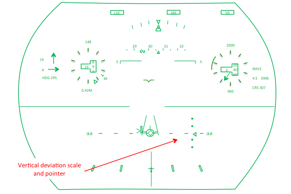
Figure: G450 HUD Vertical Deviation, from Eddie's notes.
The vertical deviation scale is available to you for either VPATH or glide slope deviation, but its accuracy varies with source. Your best bet is an ILS or MLS, followed by an LPV.
More about this below: Vertical Deviation.
Airport and Runway Symbols

Figure: G450 HUD Runway Symbol, from Eddie's notes.
If you have an ILS localizer or an MLS dialed in and set up properly, the HUD will draw you an airport symbol where it believes the runway is and it will do this 2,000 feet above the runway. When you get to 350 feet of the runway, it draws a runway symbol, complete with touchdown zone:

Figure: G450 HUD Symbology Airport versus Runway Symbols, from Eddie's notes.
More about this below: Runway Symbol.
HUD Display Controller Runway Elevation
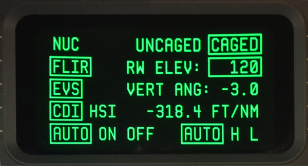
Photo: G450 Display Controller HUD Menu - Rwy Elev, from Eddie's aircraft.
[G450 Airplane Flight Manual, §02-08-80, ¶1.C.] When conducting QFE, ILS or LPV approaches using the HUD, set the runway elevation to zero on the display controller HUD menu page.
This isn't something you need to set to the nearest 10 feet, erring on the plus side. It is used to determine when the airport and runway symbols appear. If it isn't set, they won't come up at all. If they are set to QNH when QFE is being used, they may come up late.
References:
Gulfstream G450 Aircraft Operating Manual, Revision 35, April 30, 2013.
Gulfstream G450 Airplane Flight Manual, Revision 35, April 18, 2013