Hydraulic System
- James Albright (a former G450 driver)
Updated: 2019-05-10
The G450 has two hydraulic systems, one with several back ups and the other with no back ups at all. The G450 Aircraft Operating Manual and G450 Maintenance Manual are fairly obtuse and riddled with errors. Even this many years into the aircraft's life, there is still only one diagram of the hydraulic system that isn't filled with errors. That diagram, which appears here, is in the G450 Quick Reference Handbook, page EE-2.
If you have any GV or G550 experience, the G450 hydraulic system will seem very familiar. If you've flown the GIV, the system will seem similar with a bunch of name changes. If you've flown the GII or GIII, you will think all your hydraulic system prayers have been answered. We used to joke, but in this airplane it is true, "Works good, lasts a long time." For when it doesn't work, see: G450 Hydraulic System Abnormals.
Everything here is from the references shown below, with a few comments in an alternate color.
G450 Hydraulic System
Figure: G450 Hydraulic SystemG450 Quick Reference Handbook, page EE-2)
Overview
Unlike most of the G450 Systems pages on this website, we will deviate from the order presented in the G450 AOM in favor of a more logical order:
Hydraulic Pressure Sources:
Hydraulic Pressure Distribution:
Engine Driven Pumps
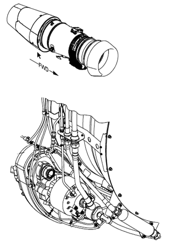
Figure: Hydraulic engine driven pump, (G450 MM, §29-12-01, figure 401)
[G450 AOM, §2A-29-20 ¶2.A.] The engine-driven hydraulic pump is mounted on the engine accessory gear box within the nacelle. Engine rotation is translated by the gear interface to spin the hydraulic pump so that the pump operates whenever the engine is running. Hydraulic pump output is rated at 3,000 psi at a pump rpm of 3,750 producing a flow of 25 gpm. Actual flow rates vary between 10.5 gpm at engine idle and 21.3 gpm at maximum engine thrust. When the engine and pump begin to turn, suction is generated in the supply line to the pump. The left supply line connects the left pump to the left hydraulic reservoir located within the aft equipment bay of the aircraft. The right supply line connects the right engine pump to the right hydraulic reservoir which is also located within the aft equipment bay of the aircraft.
The engine-driven hydraulic pump is mechanically connected to the engine, it always turns as long as the engine is turning. It puts out 3,000 psi with very little engine rpm, but the volume varies between 10 and 21 gpm.
Pressure Supply
[G450 AOM, §2A-29-20 ¶2.A.] There is no switch to disable the hydraulic pump; instead, a shutoff valve, located in the aft equipment bay, is installed in the supply line between the reservoir and the pump. The shutoff valve is powered by 28v DC from the left essential bus, and controlled by the left engine fire handle on the forward section of the cockpit center console
[G450 MM, §29-15-00 ¶3.A.] The left hydraulic system shut-off valve operates on 28 Vdc from the L HYD S/O circuit breaker and is a motor driven shut-off valve. When the valve is closed, hydraulic fluid flow is cut off to the suction side of the left engine-driven hydraulic pump. The valve controls fluid flow to the left pump.
[G450 MM, §29-15-00 ¶3.C.] The right hydraulic system shut-off valve operates on 28 Vdc from the R HYD S/O circuit breaker and is a motor driven shut-off valve. When the valve is closed, hydraulic fluid flow is cut off to the suction side of the right engine-driven hydraulic pump. The valve controls fluid flow to the right pump.
[G450 AOM, §2A-29-20 ¶2.A.] Pulling out the fire handle closes the shutoff valve, preventing hydraulic fluid from entering the engine nacelle. The shutoff valve may be physically opened or closed by positioning a pointer / handle on the valve body in the equipment bay. If the engine fails but is not shut down with the fire handle, the windmilling engine will continue to turn the hydraulic pump. An airspeed sufficient to achieve approximately 25-30% HP rpm will provide sufficient hydraulic pressure to operate the flight controls.
You cannot shut off the engine-driven hydraulic pump, but you can shut off the flow of fluid from the reservoir which effectively stops pump output. The only way you can do this is with the fire handle which will, of course, shut down the engine. If for some reason you need to stop the hydraulic pressure without shutting down the engine, you need to pull the fuel shutoff valve circuit breaker first, pull the fire handle and expect to lose that generator too. Once the hydraulic shutoff valve is closed, you pull that breaker and reseat the fire handle. That gives you your generator back.
Power Transfer Unit
The Power Transfer Unit is best understood for what it is: a hydraulically powered motor connected by an axle to a mechanically driven pump. It is designed for the day your left engine-driven hydraulic pump quits and your right engine-driven pump still works. It can drive everything on the left system except the flight controls and thrust reverser.
[G450 MM, §29-22-00 ¶1.A.] The purpose of the Power Transfer Unit (PTU) system is to produce hydraulic pressure in the left hydraulic system in the event of a left engine-driven hydraulic pump failure. The PTU hydraulic system is a backup / standby system for the left hydraulic system. The PTU pump / motor is powered by the right hydraulic system and uses left hydraulic system fluid to pressurize the left hydraulic system.
[G450 AOM, §2A-29-20 ¶2.E.]
The Power Transfer Unit (PTU) is a hydraulic motor / pump installation located in the aft equipment bay on the right side of the aircraft below the hydraulic replenisher. The motor side of the installation is driven by the right hydraulic system and controlled by a shutoff valve. The pump side is plumbed to the left hydraulic system and connected to the motor side by a common shaft. When the shutoff valve is open, the right hydraulic system is ported to the motor at thirteen (13) gallons per minute, turning the motor at thirty-nine hundred revolutions per minute (3,900 rpm) producing a flow of ten (10) gallons per minute at three thousand (3,000) psi in the left hydraulic system. The right system motor function is protected by a flow restrictor. The restrictor will prevent operation of the motor if it diverts too much flow from the right system to prevent adequate operation of the flight controls, since operation of the PTU assumes loss of the left hydraulic system and only right system pressure is available for flight controls.
The switches controlling the operation of the PTU are located on the PWR XFR UNIT of the HYDRAULIC CONT panel on the cockpit overhead. The left switch is labelled OFF / ARM, and is normally selected to the ARM position. If the switch is selected OFF, the amber NOT ARM legend in the switch will illuminate. When the switch is in ARM, the shutoff valve directing right system pressure to the motor of the PTU will open whenever left system pressure drops below fifteen hundred (1,500) psi to provide pressurization of the left system. Automatic operation will be inhibited, however, by internal pump software logic if the left system quantity is low or the right system temperature is high. The right PWR XFR UNIT switch, labelled ON, will open the shutoff valve and operate the PTU regardless of left system fluid quantity or right system temperature (the amber ON legend in the switch will illuminate when the switch is depressed to the on position).
Whenever the PTU is operating, pressurized left system fluid is available to actuate the following components:
Flaps
Landing gear
Brakes
Nose wheel steering
Ground spoilers
Standby Electrical Power System Hydraulic Motor Generator (HMG)
This list varies according to where you look because it changes between the G550 and GIV. As far as I can tell, the list of components driven by the PTU are correct in the G450 AOM and the G450 QRH diagram.
All of the hydraulic system diagrams you will find in the G450 AOM and G450 MM draw a line from the left system reservoir to the PTU through the fire shutoff switch. The only correct drawing, as of February 2013, in a Gulfstream publication available to pilots is in the G450 QRH, shown above. The distinction is crucial. If you shut the left engine down with the fire switch, the PTU does have left system hydraulic fluid available to it. The classic example, of course, is a left engine fire on takeoff. You shut the engine down and pull the fire switch, all your crucial systems are picked up automatically by the PTU.
PTU Pump
[G450 MM, §29-22-00 ¶3.A.] The PTU hydraulic pump is located in the right side of the tail compartment. The PTU is made up of a fixed displacement motor and pump. Hydraulic pressure from the right hydraulic system rotates the hydraulic motor. The hydraulic motor rotates the pump and pressurizes the left hydraulic system. The outlet port of the pump has a check valve to prevent a back flow of left hydraulic system pressure from driving the PTU in reverse. The maximum output flow capability of the PTU is 11.8 gpm. The PTU output pressure is 3000 psi. There is no hydraulic fluid crossover between the left and right hydraulic systems.
Photo: PTU Shutoff Valve, (Eddie's airplane)
One of the questions I get on a repeating basis about GV series airplanes is why we bother placing the PTU switch to NOT ARMED prior to engine shut down if we plan on starting again with the Before Starting Engines - Thruflight checklist. Why not just leave it ARMED? I believe the reason is to save on an unnecessary spool up on the PTU motor. If you go to NOT ARMED, the motor remains idle until you start the right engine again with the left engine not running. If you leave it in ARMED, the PTU motor spools up once you shut down the left engine and then spools down as the right engine winds down. When you start again you get a second spool up. So do it the way the checklist calls for. Maybe you'll prolong your PTU's life a couple of days, eh?
Operation
[G450 MM, §29-22-00 ¶4.A.] Operation of the PTU is controlled by two push-button switches located in the HYDRAULIC CONT section of the cockpit overhead panel. Manual control to turn the PTU on is provided by the PWR XFR UNIT ON switch. When selected to ON (depressed), the switch overrides the arming switch function and turns the PTU on. When the PWR XFR UNIT OFF/ARM switch is selected to armed (depressed), the PTU will automatically engage when the left system pressure drops below 1500 psi. Automatic operation of the PTU is provided with the PWR XFR UNIT ON switch in the off (extended) position and the PWR XFR UNIT OFF/ARM switch in the armed (depressed) position. The PTU arming circuit provides for automatic operation if there is 1900 psi or more right hydraulic system pressure under the following conditions:
The PWR XFR UNIT ON switch is in the off (extended) position and the OFF/ARM switch is in the armed (depressed) position
Left hydraulic system pressure is less than 1900 psi
Right system reservoir temperature is below the overheat warning temperature of 175°F (79.4°C)
Left system reservoir quantity is 0.36 gallon or more (uncompensated for temperature)
If the right system reservoir fluid temperature exceeds the overheat warning temperature of 175°F (79.4°C) or the left system fluid level drops below the low level warning quantity of 0.36 gallons, the pilot can hard select the PTU on by selecting the PWR XFR UNIT ON switch to ON.
These numbers differ slightly from the G450 AOM which, for example, says the PTU activates at 1,500 psi left system pressure, not 1,900 psi. Numbers aside, the important thing to remember is you need right system pressure and left system fluid for the thing to work.
Auxiliary Pump
[G450 AOM, §2A-29-20 ¶2.D.]
The electrically powered Auxiliary (AUX) pump is plumbed into the left hydraulic system lines and located aft of the left system reservoir on the left side of the aft equipment bay. The pump is powered by the left essential DC bus, and can produce a flow of up to 2 gallons per minute at 3,000 psi.
Older G450's are equipped with a 1 gpm aux pump.
The pump is cooled by an integral fan and protected by an overheat switch that shuts off the pump if pump temperature exceeds 300°F. The pump is also protected by an overload sensor that limits current draw by the pump. The overload shutdown can be reset by selecting the pump off then back on.
Installed below and plumbed into the pump outlet line are an AUX system acoustic muffler, pressure transmitter, pressure relief valve and a pressure filter.
Operation
[G450 AOM, §2A-29-20, ¶2.D.]
The AUX pump can provide hydraulic pressure to operate the following components essential to configuring the aircraft for approach and landing if no other means of pressurizing the left hydraulic system is available:
Flaps
Brakes
However, the AUX pump cannot effectively power both items at the same time. For instance, upon landing with the AUX pump (only) powering both brakes and flaps, moving the flap handle while braking simultaneously will result in degraded performance due to the limited fluid flow produced by the AUX pump.
It is worse than that: if the flaps are moving in that situation during landing, you will not have any brakes at all, other than what is available from the accumulator.
The AUX pump is also used to close the main cabin door, pressurize the brake accumulator and operate the landing gear and gear doors for maintenance operations. Operation of the AUX pump is controlled with six switches.
On the HYDRAULIC CONT panel on the cockpit overhead are two AUX PUMP pushbutton switches: OFF/ARM and ON. With the OFF/ARM pushbutton depressed to the normal ARM position, the AUX pump will come on whenever left system pressure falls below 1,500 psi and a brake pedal is depressed more than 10°. If the OFF/ARM switch is selected to OFF, automatic operation of the AUX pump is inhibited, and the amber NOT ARM legend in the switch is illuminated. The ON switch will operate the AUX pump regardless of left system pressure.
Any of the three main cabin door control switches will operate the AUX pump to close the cabin door, provided the DOOR SAFETY switch on the cockpit overhead panel is not selected to the ON position.
The AUX pump may also be powered to operate the landing gear and landing gear doors (on the ground only) for maintenance purposes using the ground service valve installed in the panel on the right side of the aircraft aft of the nose wheel well. The ground service valve must be held open for the AUX pump to operate.
Left System
[G450 AOM, §2A-29-20 ¶1.] The left hydraulic system supplies fluid drawn from a reservoir and pressurized by an engine-driven pump to all aircraft components and subsystems that require the additional force of hydraulic pressure for normal operation. Since left hydraulic system pressure is the only actuating force for some aircraft components and subsystems, two additional means of pressurizing the left system are incorporated to compensate for the loss of the left engine or pump: an electric Auxiliary (AUX) pump and an impeller driven by right system pressure termed the Power Transfer Unit (PTU).
The AUX pump is provided with a dedicated volume of hydraulic fluid in the left system reservoir to ensure that AUX pump pressure is available if left system fluid is lost. In addition to supplying pressurized hydraulic fluid to aircraft actuators, the left system can be used to power an electrical generator if normal engine and APU generators are not available. The Standby Electrical Power System Hydraulic Motor Generator (HMG) is a variable piston hydraulic motor that uses left system pressure to rotate a generator shaft to produce Alternating Current (AC).
The left system does most the hydraulic work on the aircraft so it has the biggest reservoir and several back ups. The left engine-driven pump can run everything on the airplane except the right engine thrust reverser, the PTU, and the right system yaw damper. The PTU can run the things you need to get the airplane back on the ground following a loss of the left engine-driven pump: flaps, landing gear, brakes, nose wheel steering, ground spoilers, and the HMG. The AUX pump is for when the chips are really down (flaps and brakes) or when working on the aircraft for preflight or post-flight (main cabin door, brake accumulator and operate the landing gear and gear doors for maintenance operations.)
Fluid Distribution
[G450 AOM, §2A-29-20 ¶2.B.] The hydraulic system is a distributed system rather than a serial system, i.e., although pressurized fluid does flow through the system, fluid remains in the system lines after the engine is shut down. When the engine is started and the engine-driven pump pressurizes the fluid in the lines, the pressure is effective almost immediately at all points in the system.
Reservoir
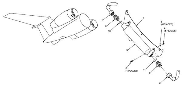
Figure: Left system hydraulic reservoir, (G450 MM, §29-16-01, figure 401, sheet 1)
[G450 MM, §29-14-00 ¶6.A.] During engine start, the engine-driven hydraulic pump begins rotating, generating pressure and creating the suction used to pull the hydraulic fluid from the reservoir through the suction line between the reservoir and pump.
Figure: Left system hydraulic reservoir level indicator, (Eddie's aircraft)
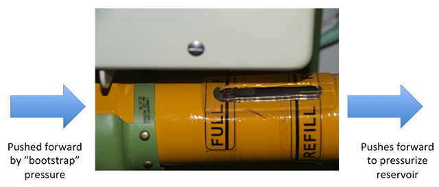
The left system reservoir is mounted on its side with a piston in the middle that pushes fluid forward (to the right in the drawing above) to pressurize the reservoir. Where does this piston gets its force? Hydraulic pressure is used to push the ram forward.
I get asked now and then why the hydraulic system has to be pressurized to measure the reservoir level. The photo tells all. The reservoir is tilted on its side and given enough time, the fluid can push the piston aft, causing the fluid level to appear higher than it is. You need hydraulic pressure to push the piston forward. I've never seen the red indicator line, ever, unless the hydraulic system is pressurized. In the photo you see that red line as full as it can get. The airplane was connected to a hydraulic mule and the system was indeed full.
Shut-off Valve
Figure: Left system hydraulic shutoff valve, (G450 MM, §29-15-01, figure 401)
[G450 MM, §29-14-00 ¶6.A.] The hydraulic shut-off valve, located in the tail compartment between the reservoir and the pump, is used to isolate the hydraulic fluid from the engine pump in an emergency. The valve is motor operated and is only energized when the fire handle in the cockpit is pulled up.
Engine-Driven Pump
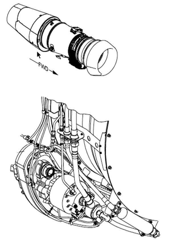
Figure: Hydraulic engine driven pump, (G450 MM, §29-12-01, figure 401)
[G450 AOM, §2A-29-20 ¶2.A.] The engine-driven hydraulic pump is mounted on the engine accessory gear box within the nacelle. Engine rotation is translated by the gear interface to spin the hydraulic pump so that the pump operates whenever the engine is running. Hydraulic pump output is rated at 3,000 psi at a pump rpm of 3,750 producing a flow of 25 gpm. Actual flow rates vary between 10.5 gpm at engine idle and 21.3 gpm at maximum engine thrust. When the engine and pump begin to turn, suction is generated in the supply line to the pump. The supply line connects the pump to the left hydraulic reservoir located within the aft equipment bay of the aircraft.
The engine-driven hydraulic pump is mechanically connected to the engine, it always turns as long as the engine is turning. It puts out 3,000 psi with very little engine rpm, but the volume varies between 10 and 21 gpm.
Acoustic Filter
Figure: Hydraulic acoustic filter, (G450 MM, §29-14-07, figure 401)
[G450 AOM, §2A-29-20 ¶2.B.] Engine pump fluid first is routed through an acoustic filter mounted within the engine nacelle that curtails noise in the hydraulic lines caused by pressure fluctuations when hydraulically powered aircraft components are activated.
The acoustic filter is also called a hydraulic damper in parts of the various manuals.
Filter Manifold
Figure: Hydraulic left manifold, (G450 MM, §29-14-01, figure 401, sheet 1)
[G450 AOM, §2A-29-20 ¶2.B.] Fluid then enters a filter manifold in the equipment bay. The manifold contains a pressurized fluid filter, a fluid return filter, an AUX pump return filter and an engine pump and PTU case drain return filter. Locating all filters within a common manifold allows access to the replaceable elements of the filters without draining system hydraulic fluid. The filter manifold also contains a pressure switch and a pressure transmitter. The pressure switch is used to monitor pump operation and signal automatic activation of the AUX pump (when the AUX pump is armed) if system pressure drops below 1,500 psi. The pressure transmitter supplies data to the Modular Avionics Units (MAUs) for formatting and presentation on cockpit synoptic and system displays.
Accumulator
Figure: Hydraulics accumulator gauges, (G450 MM, §29-17-00, figure 404)
[G450 AOM, §2A-29-20 ¶2.B.] From the filtration manifold in the aft equipment bay, fluid enters supply lines back to the engine nacelle to power the engine thrust reverser doors and forward and aft within the fuselage to system powered components. The thrust reverser supply line contains the left system accumulator that is charged through a connection to the ground service panel on the underside of the aircraft. The accumulator contains 50 cubic inches of nitrogen and is serviced to 1,200 psi at 70°F with the system unpressurized.
The accumulator is on the thrust reverser line as a matter of convenience; it is the only pressurized line from the manifold back to the engine.
Left Hydraulic System Components
The left system drives the following components:
Ailerons
Elevators
Flaps, Horizontal Stabilizer
Hydraulic Motor Generator
Landing Gear
Nose Wheel Steering
Rudder
Spoilers
Stall Barrier
Thrust Reverser (Left)
Wheel Brakes
Heat Exchanger
[G450 AOM, §2A-29-20 ¶2.B.] Lines run aft to supply the elevators, stick pusher and rudder / yaw damper, and forward to the ailerons, spoilers, speedbrakes, flaps, landing gear and doors, brakes, nose wheel steering and main cabin door. After pressurizing aircraft subsystems and components, system fluid enters a radiator type heat exchanger located in the left wing fuel tank. The hot hydraulic fluid is cooled by fuel in the tank (and tank fuel is slightly warmed, although the high ratio of fuel to hydraulic fluid results in a minimal temperature rise) then returned to the system reservoir, after passing through a system return filter located in the filtration module. A temperature transducer samples system fluid temperature just prior to the reservoir
Fluid Return
[G450 MM, §29-14-00 ¶6.A.] If the engine-driven pump volume output exceeds system requirements, fluid leaves the pump through a check valve in the pump’s case drain port, passes through a quick-disconnect in the engine strut and travels to the filter manifold. At the filter manifold, the fluid passes through a filter, a springloaded pressure relief valve and another filter before returning to the system reservoir.
Right System
The right hydraulic system was called the "flight system" back in the GII/GIII because that's all it did: flight controls. In the G450 the right system also handles the right engine thrust reverser and the PTU. If you lose the right system but still have the left, the right engine thrust reverser is the only thing you have lost. The right system hydraulics flow in a continuous loop from the reservoir to an engine-driven pump and the individual components. Along the way there are filters and valves.
Fluid Distribution
[G450 AOM, § 2A-29-20 ¶2.B.] The hydraulic system is a distributed system rather than a serial system, i.e., although pressurized fluid does flow through the system, fluid remains in the system lines after the engine is shut down. When the engine is started and the engine-driven pump pressurizes the fluid in the lines, the pressure is effective almost immediately at all points in the system.
Reservoir
Figure: Hydraulic right system reservoir, (G450 MM, §29-16-02, figure 401)
[G450 MM, § 29-14-00 ¶6.A.] During engine start, the engine-driven hydraulic pump begins rotating, generating pressure and creating the suction used to pull the hydraulic fluid from the reservoir through the suction line between the reservoir and pump.
Shut-off Valve
Figure: Right system hydraulic shutoff valve, (G450 MM, §29-15-03, figure 401)
[G450 MM, § 29-14-00 ¶6.A.] The hydraulic shut-off valve, located in the tail compartment between the reservoir and the pump, is used to isolate the hydraulic fluid from the engine pump in an emergency. The valve is motor operated and is only energized when the fire handle in the cockpit is pulled up.
Engine-Driven Pump
Figure: Hydraulic engine driven pump, (G450 MM, §29-12-01, figure 401)
[G450 AOM, §2A-29-20 ¶2.A.] The engine-driven hydraulic pump is mounted on the engine accessory gear box within the nacelle. Engine rotation is translated by the gear interface to spin the hydraulic pump so that the pump operates whenever the engine is running. Hydraulic pump output is rated at 3,000 psi at a pump rpm of 3,750 producing a flow of 25 gpm. Actual flow rates vary between 10.5 gpm at engine idle and 21.3 gpm at maximum engine thrust. When the engine and pump begin to turn, suction is generated in the supply line to the pump. The supply line connects the pump to the left hydraulic reservoir located within the aft equipment bay of the aircraft.
The engine-driven hydraulic pump is mechanically connected to the engine, it always turns as long as the engine is turning. It puts out 3,000 psi with very little engine rpm, but the volume varies between 10 and 21 gpm.
Acoustic Filter
Figure: Hydraulic acoustic filter, (G450 MM, §29-14-07, figure 401)
[G450 AOM, §2A-29-20 ¶2.B.] Engine pump fluid first is routed through an acoustic filter mounted within the engine nacelle that curtails noise in the hydraulic lines caused by pressure fluctuations when hydraulically powered aircraft components are activated.
The acoustic filter is also called a hydraulic damper in parts of the various manuals.
Filter Manifold
Figure: Hydraulic acoustic filter, from G450 MM, §29-14-07, figure 402)
[G450 AOM, §2A-29-20 ¶2.B.] Fluid then enters a filter manifold in the equipment bay. The manifold contains a pressurized fluid filter, a fluid return filter, an AUX pump return filter and an engine pump and PTU case drain return filter. Locating all filters within a common manifold allows access to the replaceable elements of the filters without draining system hydraulic fluid. The filter manifold also contains a pressure switch and a pressure transmitter. The pressure switch is used to monitor pump operation and signal automatic activation of the AUX pump (when the AUX pump is armed) if system pressure drops below 1,500 psi. The pressure transmitter supplies data to the Modular Avionics Units (MAUs) for formatting and presentation on cockpit synoptic and system displays.
Accumulator
Figure: Hydraulics accumulator gauges, (G450 MM, §29-17-00, figure 404)
[G450 AOM, §2A-29-20 ¶2.B.] From the filtration manifold in the aft equipment bay, fluid enters supply lines back to the engine nacelle to power the engine thrust reverser doors and forward and aft within the fuselage to system powered components. The thrust reverser supply line contains the left system accumulator that is charged through a connection to the ground service panel on the underside of the aircraft. The accumulator contains 50 cubic inches of nitrogen and is serviced to 1,200 psi at 70°F with the system unpressurized.
The accumulator is on the thrust reverser line as a matter of convenience; it is the only pressurized line from the manifold back to the engine.
Right Hydraulic System Components
The right system, in conjunction with the left system or as a single pressure source, provides power to the following dual system actuators:
Ailerons
Elevators
Rudder
Spoilers
Thrust Reverser (Right)
PTU motor
Heat Exchanger
[G450 AOM, § 2A-29-30 ¶2.B.] Right system pressurized fluid follows a similar path as the left system, through the same sequence of acoustic filter, filter manifold, system accumulator, dedicated thrust reverser, to the tail-mounted flight controls and forward to the landing gear wheel well for powering the flight controls installed on the wing, through a pressure relief valve, into the radiator cooler in the right wing fuel tank hopper, through a return filter and back to the reservoir. The right system also includes plumbing to the motor section of the PTU and return.
Fluid Return
[G450 MM, §29-14-00 ¶6.A.] If the engine-driven pump volume output exceeds system requirements, fluid leaves the pump through a check valve in the pump’s case drain port, passes through a quick-disconnect in the engine strut and travels to the filter manifold. At the filter manifold, the fluid passes through a filter, a springloaded pressure relief valve and another filter before returning to the system reservoir.
Differential Pressure Indicators
An entire section on hydraulic system DPIs? Why is that necessary? It is because there is some confusion about them and when they can be reset by a pilot and when they cannot. It helps to know where they are and which one of those little buttons belongs to which system. And then all you really need to know is you, the pilot, can only reset one of the ten. For the other nine, it takes a mechanic and a check procedure. Having said that, let me clarify. The procedure for resetting the PTU manifold DPI is in the operating manual and simply involves pushing the DPI and making a log entry. For the others, the procedures are in the maintenance manual and involve several steps including a system check with the applicable system pressurized. If you are flying commercially in the U.S., a pilot cannot do this. But even if you are flying under other rules, I believe you need to be trained. Of course this is just my opinion.
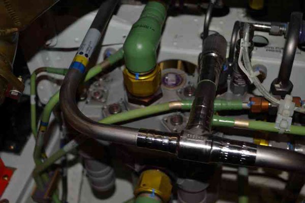
Photo: Left Hydraulic System Manifold, (Eddie's aircraft)
They teach you in school that the left system has five DPIs, the right system has three, and the Aux and PTU each have one. That is wrong. Think of it this way. Each DPI is a check on a filter and there are ten in total:
The left engine pump has a bypass filter, located on the left manifold.
The right engine pump has a bypass filter, located on the right manifold.
The left hydraulic system has a main pressure filter, located on the left manifold.
The left hydraulic system has a main return filter, located on the left manifold.
The right hydraulic system has a main pressure filter, located on the right manifold.
The right hydraulic system has a main return filter, located on the right manifold.
The PTU has a bypass filter, located on the left manifold.
The PTU has a pressure filter, located above its dedicated filter above the PTU itself.
The Aux pump has a return filter, located on the left manifold.
The Aux pump has a pressure filter, located above its dedicated filter below the aux pump itself.
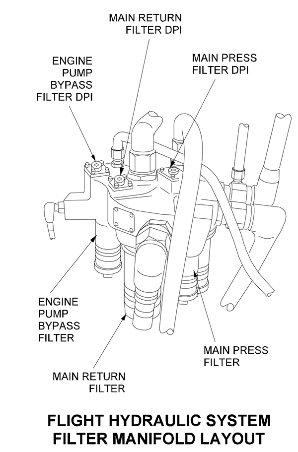
The Left Hydraulic System Manifold
Figure: Manifold Filters and Differential Pressure Indicators, (G450 Maintenance Manual, §29-14-01, Figure 601, Detail B)
Much of what appears in the G450 Maintenance Manual comes from the GIV Maintenance Manual and in that airplane the left system is called the "combined system." Looking at the manifold, you see five DPIs of which only two belong specifically to the left system, one belongs to the engine, one belongs to the "Utility Pump Bypass Filter" (which was what the PTU was called in the GIV), and the final one belongs to the auxiliary pump.
In my opinion, you, as a pilot, are not allowed to reset any of these. It takes a mechanic who will then have to run the procedures in the G450 Maintenance Manual, §29-14-01, Page 603. (This requires the system be run at "full pressure and maximum flow during normal operation" followed by a check of the DPI. If it pops again, the filter must be replaced.)
The Right Hydraulic System Manifold
Figure: Manifold Filters and Differential Pressure Indicators, (G450 Maintenance Manual, §29-14-01, Figure 601, Detail A)
Much of what appears in the G450 Maintenance Manual comes from the GIV Maintenance Manual and in that airplane the right system is called the "flight system." Looking at the manifold, you see three DPIs of which only two belong specifically to the right system, one belongs to the engine.
In my opinion, you, as a pilot, are not allowed to reset any of these. It takes a mechanic who will then have to run the procedures in the G450 Maintenance Manual, §29-14-02, Page 603. (This requires the system be run at "full pressure and maximum flow during normal operation" followed by a check of the DPI. If it pops again, the filter must be replaced.)
The Aux Hydraulic System Manifold
Figure: Auxiliary pump pressure filter DPI, (Eddie's aircraft)
The aux pump pressure filter DPI is on the left side of the aircraft, underneath the aux pump itself.
In my opinion, you, as a pilot, are not allowed to reset this DPI. It takes a mechanic who will then have to run the procedures in the G450 Maintenance Manual, §29-25-01, Page 601. (This requires the system be run at "full pressure and maximum flow during normal operation" followed by a check of the DPI. If it pops again, the filter must be replaced.)
The PTU Manifold
Figure: PTU filter DPI, (Eddie's aircraft)
This is the only DPI of the ten you can reset. Why are you allowed to reset it? Because the AOM says you can:
[G450 Airplane Flight Manual §2-01-20]
83. Power Transfer Unit (PTU) DPI (1) — Check
NOTE: Ensure DPI is flush. If DPI is popped, reset DPI and note time in logbook. Continued operation for the next fifty (50) flight hours is allowed. Check DPI prior to each flight.
What do you do if you (the pilot) cannot reset a DPI?
Photo: Left hydraulic system main pressure filter DPI popped, (Eddie's aircraft)
As silly as it may seem, if you have a popped DPI other than the PTU, you need a qualified mechanic to reset it. We had one of the DPIs on the left system manifold pop when in Luton, England. Fortunately there is a Gulfstream service center where a mechanic reset it for us and watched us perform the maintenance manual procedure which is to pressurize the system, run the flight controls and then make sure the DPI hasn't repopped. Since we didn't want to hook up a hydraulic mule, we ran the left engine. The entire episode, from start to finish, took about 30 minutes. Since we are operating under Part 91 and didn't want this to happen again, we had each of our pilots trained in the procedure and documented the training. We had to do this once without a mechanic before getting the DPI replaced. If we were operating under commercial rules in the U.S., we would not have been able to do this.
Servicing on the Road
For years our aircraft's hydraulic system never varied in quantity except right after some kind of maintenance. But when that happened, the mechanics took care of it. But when on the road with limited (or reluctant) maintenance options, things change.
Dear Eddie,
I was on the road with my trusty G450 when the right hydraulic system synoptic showed us at 0.6 gallons, a bit low. Since it was so close to the "low" mark on the synoptic we decided to look at the actual mark on the reservoir piston after we landed. But there was nothing to see. We ended up flying home like that and got a "right hydraulic quantity low" CAS message just before landing. Our mechanics said we should have serviced it. But we were never taught how. Please teach us.
Signed, R. Fader
Fort Lee, New Jersey
Mister Fader,
As luck would have it, I was in the exact same situation a while back and I had never been trained either. We called in a local mechanic with GIV experience but he said the system was fine, since the digital readout in the aft equipment said the system was full. So he was no help. You may have noticed that the reservoir sits on its side and you may have heard that it takes "bootstrap" pressure to keep the reservoir properly pressurized. What that means to us pilots is that the engine has to be running to get a proper quantity indication. (Your mechanic can hook up an external source of pressure from a contraption known as a "mule" for some reason.) I took a few photos to communicate with our mechanic. Here is what we saw before we shut the engines down:
Photo: G450 Right hydraulic system low synoptic, Eddie's aircraft
Click photo for a larger image
So we shut the engines down and looked at the reservoir indicator:
Photo: G450 Right hydraulic system reservoir piston, unpressurized, Eddie's aircraft
I thought I could at least get a sense of the quantity but there is no indicator in sight. Turns out it was full scale to the right, since all that fluid was no longer pressurized. So next step was the digital readout:
Photo: G450 aft equipment hydraulic reservoir indicator, left, Eddie's aircraft
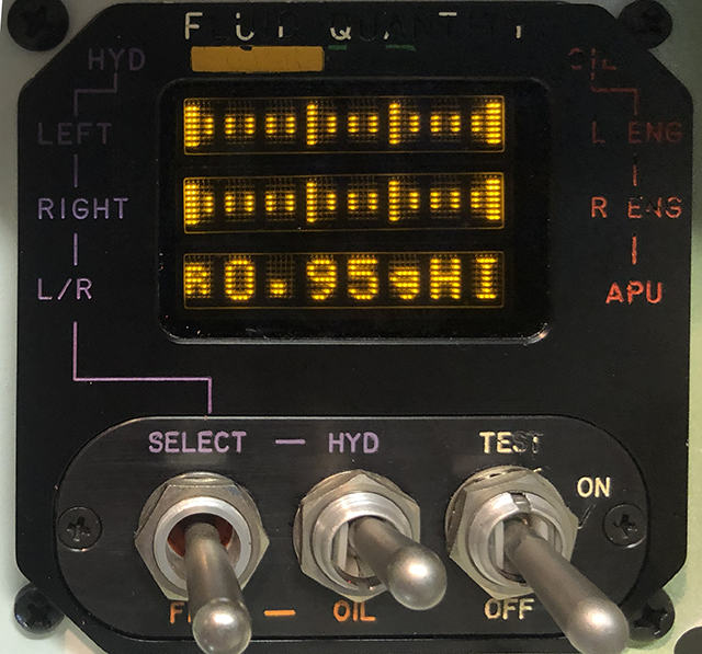
It is the same indicator you use when servicing engine oils, except you select "HYD" instead. Unlike the oils, you only see one side at a time and the system defaults to the left. You need to push the "SELECT" switch up once to get the right system:
Photo: G450 aft equipment hydraulic reservoir indicator, right, Eddie's aircraft
So, as you can see, it shows the right system at 0.95 gallons and "HI" which I assume means the quantity is registering at higher than that. But we know this is unpressurized. So I started the right engine and the quantity knocked down to 0.7 gallons, low but higher than what we saw in the cockpit. The reservoir piston showed us almost full:
Photo: G450 Right hydraulic system reservoir piston, pressurized, Eddie's aircraft
Our mechanic emailed us the applicable sections from the maintenance manual: (I am only showing the applicable portions)
[G450 MM, §12-15, ¶1.B3] Servicing reservoir with onboard replenisher
(3) Apply 3000 psi of hydraulic power to applicable system.
(4) Rotate selector valve (3) to applicable hydraulic system.
(5) On ground service panel (7) select GND SVC BUS SW (6) to ON.
(6) Hold replenisher pump switch (4) to ON until reservoir gage (2) indicates FULL.
NOTE: Do not overfill reservoirs (Max capacity is 3.66 gallons, full is 2.75 gallons left system, 0.8 gallon right system).
(7) Rotate selector valve (3) to OFF.
(8) . . . (9)(c)
(9) (d) Repeat Step 1.B3.(3) thru Step 1.B3.(7) and service reservoir until cockpit indicator indicates FULL.
Photo: G450 aft equipment hydraulic replenishing panel, Eddie's aircraft
Our mechanic explained that the digital reservoir indicator in the aft equipment bay is not temperature compensated and that is why the manual requires you to judge using the cockpit indicator. So I had the other pilot in the cockpit running the engine and watching the synoptic. I selected "Right" from the reservoir handle, lifted the red guarded switch and added fluid until I saw 0.8 gallons. I ran to the cockpit and found the synoptic had only gone to 0.6 gallons. We agreed that I would go back and add fluid until the other pilot saw 0.8, at which point he would move the elevator back and forth. I would see the cables move (they are on the left side of the airplane) and stop the refill. And that is exactly what happened. The digital readout in aft equipment read 0.95 but the cockpit synoptic read 0.8 gallons. When you are done, make sure all the handles and switches are back to their original "off" and guarded positions.
The next flight, all was better:
Photo: G450 hydraulics synoptic, the next flight, Eddie's aircraft
If you want to do this, I recommend you have your mechanic give you some hands on training and then document the fact you had been trained.
Eddie
References:
Gulfstream GIV Operating Manual, Revision 9, October 11, 2002
Gulfstream GIV Airplane Flight Manual, Revision 30, 11 October 2002
Gulfstream GV Aircraft Operating Manual, GAC-AC-GV-OPS-0002, Revision 30, May 13, 2008
Gulfstream GV Airplane Flight Manual, Revision 30, 13 May 2008
Gulfstream GV Illustrated Parts Catalog, Revision 24, August 31, 2005
Gulfstream GV Maintenance Manual, Revision 25, August 31, 2005
Gulfstream GV, GV-SP, GV-SP (G550), GV-SP (G500), GIV-X, GIV-X (G450), GIV-X (G350) Master Minimum Equipment List, Revision 07, February 4, 2010.
Gulfstream G450 Aircraft Operating Manual, Revision 35, April 30, 2013.
Gulfstream G450 Airplane Flight Manual, Revision 36, December 5, 2013
Gulfstream G450 Illustrated Parts Catalog, Revision 17, October 31, 2012
Gulfstream G450 Maintenance Manual, Revision 18, Dec 12, 2013
Gulfstream G450 Quick Reference Handbook, GAC-AC-G450-OPS-0003, Revision 34, 18 April 2013


