Landing Gear Abnormals
- James Albright (a former G450 driver)
Updated: 2017-05-13
The procedures are pretty cut and dried. Of course you should consider that this landing gear system has been used ever since the G-159 — the "Gee One" — and the main gear has always come down and only twice has the airplane been landed without the nose gear. Remember calling Gulfstream Tech Ops, 800-810-4853, can get you in touch with the guys who practice these things for a living. More about: G450 Landing Gear.
Everything here is from the references shown below, with a few comments in an alternate color
Abnormal Gear Condition - Emergency Landing

Symptoms
An unsafe gear condition will be signified by a missing "down and locked" green light, a red light in the gear handle, an indication on the synoptic page, and possibly one or more CAS messages:
Main Gear Not Down, L-R
Main Gear Door Open, L-R
Nose Gear Not Down, L-R
Nose Gear Door Open, L-R
Analysis
If any of the gear fail to extend, you can attempt G-forces to knock them free. With a nose gear locked up, you can even try jarring it loose by touching down on the main gear while keeping the nose airborne. If unable to extend at least two of the three gear, you should retract the gear and land with all the gear up.
Procedure: Nose Gear Retracted, Both Main Gear Down and Locked
[G450 Airplane Flight Manual §4-18-30]
NOTE: If contamination of the uplocks due to ice and snow is suspected, consider flying to an area where melting can occur. If fully retracted, attempt to release from uplocks by applying positive “g” loading not to exceed 2.5g with flaps UP. If partially extended but not locked down, perform a normal approach and firmly bump the main wheels on the runway in an attempt to shake the nose gear down and locked. Execute go-around. Consideration should be given to flying faster than normal in order to increase elevator effectiveness and the nose falling through on touchdown.
Landing procedure:
GPWS/GND SPLR FLAP ORIDE . . . ON
GPWS Voice Override . . . ON
Touchdown . . . RUNWAY CENTERLINE
Remember the nose tends to pivot downward if you touchdown with enough force, you may need momentary back pressure to keep the nose off the runway.
Speed Brakes . . . EXTEND AS NECESSARY
Thrust Reversers . . . USE MAXIMUM (BOTH ENGINES)
Wheel Brakes ... USE MINIMUM
Nose ... FLY ONTO RUNWAY
Relieve weight with elevator after runway contact.
Brakes . . . AS NECESSARY FOR DIRECTIONAL CONTROL AND STOPPING
Procedure: One Main Gear and Nose Gear Down and Locked, Opposite Main Gear Retracted
[G450 Airplane Flight Manual §4-18-40]
If fully retracted, attempt to release from uplocks by applying positive “g” loading not to exceed 2.5g with flaps UP (0°).
If partially extended, attempt to lock unsafe gear down. Yaw the airplane to apply spanwise air load to force the affected gear outboard; left rudder for left main gear, right rudder for right main gear.
Landing procedure:
GPWS/GND SPLR FLAP ORIDE ... ON
Touchdown ... SIDE OF RUNWAY WITH SAFE GEAR
NOTE: Ground spoilers and thrust reversers will not be available with one main gear retracted.
Speed Brakes ... EXTEND
Brakes ... AS NECESSARY FOR DIRECTIONAL CONTROL AND STOPPING
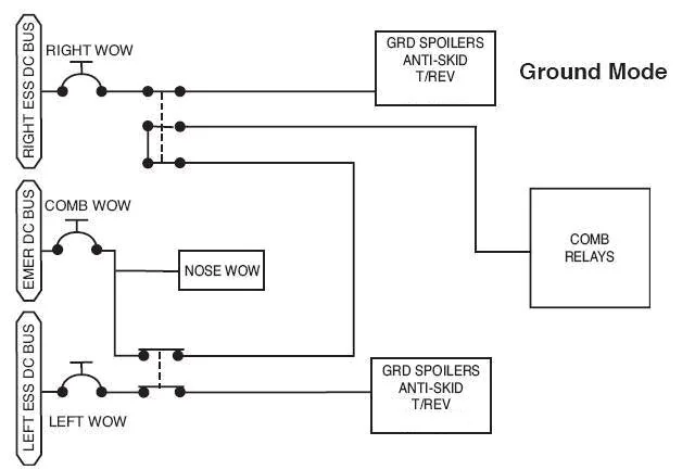
NOTE: Nosewheel steering is unavailable in this configuration. Both main gear Weight-On-Wheels (WOW) and Combined WOW must be in the GROUND mode to enable steering.
Unsafe Gear ... RELIEVE WEIGHT WITH AILERONS
Procedure: Two Gear Unsafe
[G450 Airplane Flight Manual §4-18-50]
One Main Gear Only Down and Locked
If only one main gear is extended, retract gear, see Landing Gear Retraction Following Alternate Extension, and perform an all gear up landing. See All Gear Up Landing Procedure.
Both Main Gear Retracted, Nose Gear Down & Locked
If unable to extend and lock down main gear, retract nose gear and perform an all gear up landing. See Landing Gear Retraction Following Alternate Extension.
Procedure: All Gear Unsafe

[G450 Airplane Flight Manual §4-18-70]
NOTE: Do not deploy spoilers for this procedure.
Landing Fuel ... 2000 POUNDS MAX
Airplane ... DEPRESSURIZE
CABIN PRESS CONTROL ... MANUAL
TROV ... FULL OPEN
GPWS/GND SPLR FLAP ORIDE ... ON
Final Approach Configuration ... FLAPS 39° / VREF
NOTE: Use final approach speed of VREF or as slow as possible at all planned wheels-up landing weights and fly a very shallow approach angle.
Elevator Trim ... SET TO DEVELOP MAX NOSE-UP MOVEMENT
NOTE: A slight control column push may be required to maintain proper pitch attitude.
Sink Rate ... TARGET LOW AT TOUCHDOWN
NOTE: Flap segments are likely to break clean away from the wing at touchdown.
Touchdown ... RUNWAY CENTERLINE
NOTE: When aft fuselage contacts runway surface, immediately shut down both engines with FIRE handles.
After Touchdown:
Directional Control ... MAINTAIN WITH RUDDER
NOTE: Pull control column to the full aft position during the remainder of the ground run to maintain a nose-high attitude.
Both FIRE HANDLES ... PULL
NOTE: When aft fuselage contacts runway surface, immediately shut down both engines with FIRE handles.
APU MASTER ... OFF
LEFT AND RIGHT MAIN BATTERIES ... OFF
When Stopped:
Passengers / Crew ... EVACUATE IMMEDIATELY
Anti-Skid Failure
A takeoff abort without anti-skid could be a problem, especially if the numbers are close. A landing, however, should be a non-event under most circumstances. You can get performance numbers from a variety of sources but the conservatism factor might change where you want to go:
The G450 PC, page 27, simply tells you to increase your landing distance by 173%. If you have the runway, this satisfies the need and your are done easily.
The G450 PH, page PC-14, gets you by with a much smaller increase at normal landing distances, as little as 48%. When using this chart, keep in mind these numbers have already been factored by 1.67 to allow for the 14 CFR 135 60% rule.
The G450 AFM, page 5.11-10, gives you what you need for a variety of conditions.
CAS:
Antiskid Fail
Symptoms
You may or may not get the indicated CAS message as well as WOW messages.
Analysis
G450 QRH, §MB-13 cites:
Miscomparison in 28V DC power supplies, or
Miscomparison in WOW switches, or
System circuit problems, or
Auxiliary hydraulic system failed to energize or pressure failed to rise within 3 seconds after brake pedals were depressed.
Procedure
[G450 AFM, §3-18-20]
Before takeoff:
NOTE: If performing a takeoff with anti-skid inoperative or selected OFF, flight crew should review AFM Section 5, Performance, to assess the takeoff distance penalties.
During takeoff with anti-skid inoperative or selected OFF, if the takeoff is aborted, proceed as follows:
Power Levers ... IDLE
Speed Brakes ... EXTEND
Maximum Reverse Thrust ... APPLY
Brakes ... APPLY 400 PSI MAXIMUM APPLIED BRAKE PRESSURE
Before landing:
NOTE: Brake pedal position in relation to brake pressure can be observed and practiced airborne with the ANTI-SKID switch selected to OFF, and the landing gear up. When the ANTI-SKID switch is selected to OFF, the pressure scales depicted on the Brakes system page change to provide improved monitoring of brake application pressures.
ANTI SKID ... VERIFY ON
NOTE: With the ANTI-SKID switch left ON, there may still be partial anti-skid protection available, depending on the nature and level of failure. With the ANTI-SKID switch OFF, all anti-skid protection is disabled.
Brakes System Page ... SELECT
Braking ... ASSUME FULL ANTI-SKID FAILURE
After landing:
Maximum Reverse Thrust ... APPLY
Brakes ... APPLY 400 PSI MAXIMUM APPLIED BRAKE PRESSURE
CAUTION: IT IS NORMAL FOR DECELERATION TO INCREASE AS THE STOP PROGRESSES. THIS MAY RESULT IN LOCKED WHEELS AND BLOWN TIRES. REDUCE PRESSURE AS REQUIRED TO MAINTAIN CONSTANT DECELERATION. THERE WILL BE A SIGNIFICANT INCREASE IN LANDING DISTANCE WITH ANTI-SKID INOPERATIVE.
NOTE: An increase in landing distance will result if a landing rollout is made with the anti-skid inoperative. For landing distances, refer to AFM Section 5: Final Approach and Landing, Landing Field Length, Anti-Skid Inoperative. Use of reverse thrust will aid in reducing required landing field length.
Attempted Gear Retraction With Pins Left in
They say there are those who have and those that will takeoff with the gear pins installed. Well, I don't believe that, but those guys exist. You get busy, you get distracted. We had a crew at Andrews do that in a GIII. And then there was the story of my old GV flight department. As the new guy I insisted on making a production of showing those guys the three pins. Those guys thought that was unnecessary . . . until the day they were flying together, without me, and nobody removed the pins. There are two issues here, both will burn you.
Symptoms
From simulator tests:
The gear handle will move to the up position.
The gear will not move and noise levels should increase with airspeed.
You should get amber "Main Gear Not Up" and "Nose Gear Not UP" CAS Messages as well as a cyan "Service Door" CAS message.
The doors synoptic page will show all three gear doors open.
The gear handle can be lowered. The amber CAS messages will extinguish but the cyan "Service Door" message remains.
If you do not press the dump switch, braking may or may not be normal. (I've heard it can go either way.) The simulator was unable to try the gear retract solenoid scenario discussed below.
Brakes
[Gulfstream Breakfast Minutes, 18 Jan 2013]
A G450 operator contacted Technical Operations with the following landing gear issue. After takeoff, the crew selected the landing gear handle to the up position, but all three landing gear failed to retract. The landing gear handle was free to move and was not impeded by the landing gear handle lock release button. It was also observed that the landing gear control circuit breaker was not extended or “popped.” All hydraulic systems were operating normally.
At this point, the crew selected the landing gear handle down and elected to return to the departure airport, where they made an uneventful landing.
After parking on the ramp, the crew discovered that all three landing gear actuator pins had been left installed. They also noted that the brakes seemed to be “dragging” considerably during taxi to the ramp.
A review of the incident determined that the flight crew did not follow the landing gear failure to retract procedure. This procedure is located in the Quick Reference Handbook (QRH), page EG-3, and the Airplane Flight Manual (AFM), page 3-113. Both instances point out that once the landing gear handle is placed in the down position (after a failed retraction), the landing gear dump valve switch must be pressed and held for three seconds. The selection of the DUMP switch will not affect the dump system or illuminate the switch capsule, but will provide an alternate electrical ground path for energizing the normal landing gear extend solenoid. This will return the landing gear system to the normal landing gear extended configuration for landing. Once performed, this allows normal nose wheel steering and brake functionality for landing.
The flight crew did select the gear handle to the down position after the failed retraction; however, they did not press the landing gear DUMP switch for three seconds. This left the landing gear out of sequence, which affected nose wheel steering and braking functionality. This is in reference to the condition the crew reported after landing regarding the dragging brakes.
The aircraft was then taken to the hangar and placed on jacks. The landing gear system was reset to the normal condition. All landing gear normal and emergency operational checks were completed, as well as a check of the brake and nose wheel steering systems. No faults were found, and all systems operated normally.
This incident stresses the importance of following established procedures (pre-flight and in-flight) and notes the delays that can be encountered when procedures are not followed.
The story in the Breakfast Minutes left a few details out. The pilot in the right seat said it felt like they were landing with autobrakes and once they stopped, the airplane would not move. The runway had to be closed. Don't be one of those guys.
We in the business of teaching these airplanes tend to emphasize the dragging brakes as a reason to remember that there is a checklist for this procedure. I suppose you will be pretty angry when you realize you are going to have to return and it is your fault. I think anger can cause us to make bad situations worse. Well, keep calm but the problem is even worse than we previously thought . . .
Gear Retract Solenoid

The initial news reports say that on April 11, 2017, a G450 took off from Salzburg Airport with the landing gear safety pins still installed. The pilots returned, landed, pulled the pins, and the nose gear retracted. But there was more to it than that. Here is what I heard happened:
The pilots forgot to remove the landing gear safety pins.
The pilots took off, attempted to retract the landing gear, which did not because of the safety pins. The pilots returned the gear handle to the extend position.
The pilots did not complete the "Landing Gear Failure to Retract" or "Attempted Landing Gear Retraction With Safety Pins Installed" checklists, either of which would have had them press and hold the landing gear dump valve switch for three seconds.
The pilots landed, removed the pins, and upon activating the AUX pump the nose gear retracted.
Most of us realize the landing gear hydraulic lines serve two functions, depending on where the landing gear hydraulic control (selector/dump valve) is in its sequence. More about this: G450 Landing Gear Control. The retraction lines becomes extension lines and the extension lines become retraction lines depending on where the valve is. In older Gulfstreams you could predict where this valve was by looking at the gear handle. The solenoid sat right below the gear handle through a mechanical linkage. On newer Gulfstreams the gear handle is an electrical switch and the valve sits in between the main landing gear wheel wells, controlled by an electrical solenoid. But we often forget that once the gear handle is raised, that valve moves to the retract position until it completes its sequence. The retract lines cannot become extension lines until the pressure is relieved. That's why you need the dump valve in this situation. What about the role of the aux pump in all this?
[G450 Maintenance Manual, §32-38-00, ¶4.A.] The nose landing gear normally receives hydraulic power from the left hydraulic system. Should the left system fail, but retain left system fluid, the power transfer unit can provide pressurized left system fluid to the nose landing gear. The auxiliary pump can be used as a backup source for the nose wheel steering system and can provide pressure to the nose landing gear and doors for ground service operation only.
Of course this begs the question about the mains: why didn't the main landing gear also retract? Two reasons. First, the aux pump is very weak and the nose gear mechanical over-center downlock is pretty flimsy. If you don't know what a "suitcase spring" is, see: G450 Landing Gear Uplocks and Downlocks. They are very weak and are the reason you should always rush to insert the nose gear pins and never remove them if you expect any kind of jostling with a tug. Secondly, the aux pump is very weak and there is a lot of weight on those main gear struts. Unlike the nose, the main gear downlocks are very secure.
This incident has made me rethink just how much on an expert I really am. I knew the aux pump could lift the nose gear while on the ground because the nose gear over-center link is very weak. I knew about both checklists cited below and the requirement to press and hold the dump valve for three seconds. I knew you would have problems with the anti-skid if you didn't do that. But when I heard the nose gear retracted under these circumstances, I was surprised. That is yet another reason to know which checklists exist for which procedure and to the use them. These airplanes are too complicated for we pilots to really understand. None of us are experts anymore.
The Checklist You Should Use WHENEVER the Gear Fails to Retract . . .

. . . but if you forgot:

Now what?
This begs another question: if you have this happen to you, even if you remembered to press and hold the dump switch for three seconds, should you have the aircraft inspected? Do you need to put the airplane on jacks to do a gear swing? My systems knowledge says no, but these airplanes are so complex and my systems knowledge relatively limited, that the paranoid pilot in me says yes. At the very least, you should call Gulfstream and get them to commit one way or another. (A bad decision here will probably cost you your job and prevent you from getting another.) This could end up being a huge deal. So let's exercise some caution before any of this happens .
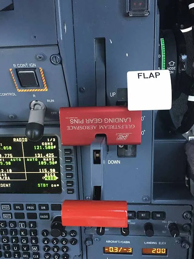
Photo: G450 Gear pin holder / gust lock block
At least ten years ago Gulfstream started delivering airplanes with a gear pin holder with a notch in it that allows the thing to be stored on the gust lock handle. I must admit that I often react to such things as gimmicks and did not use this small metal block in this way. When the gear pins were installed, the holder was in the little cabinet on the side of the main entrance door. But if you think about it, that little block does several things for you, provided you apply a little discipline. Whenever the gear pins are installed, that block should be on the gust lock handle. As soon as the gear pins are removed, they should be put into that metal block. What does this do for you? First, if you follow this procedure you will never forget to remove the pins prior to departure because the flap handle will not move with the holder on the gust lock handle. Second, you will never forget the gust lock handle for the same reason. This will necessitate one change to the way many of us operate. We tend to store the aircraft at our home hangars with the flaps in the 10° position to facilitate preflight inspections. The flap handle needs to be up for this block to fit. There are lots of advantages to storing the airplane with the flaps up and delaying the inspection of the area forward of the flaps until you have AC power is what we G450 guys do any way when on the road. (GV and G550 operators don't have the same flap/stab issues as us guys in the G450.)
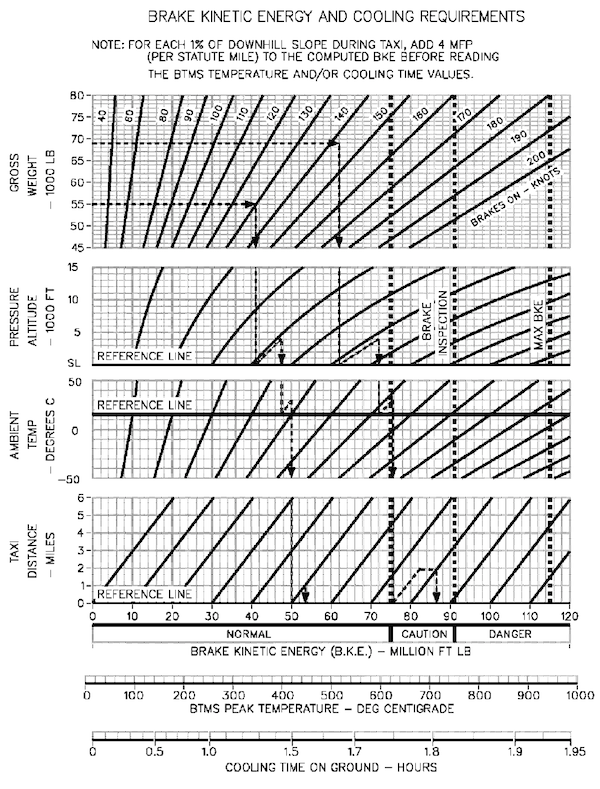
Brake System Overheat Indication
The G450's Brake Temperature Monitoring System (BTMS) keeps an eye on brake system energy limits for you but you should have a working knowledge of the Brake Kinetic Energy and Cooling Requirements Chart in the G450 AFM, Appendix C for two reasons: (1) it lets you know when you have to evacuate the aircraft and quarantine it for possible wheel and brake explosions, and (2) it lets you know when it will be okay to make a subsequent takeoff.
You do not have a cockpit indication of brake energy in terms of million foot-pounds of energy but you do have four readouts, one per brake heat pack, of brake temperature. The normal, caution, and danger zones are important to you:
75 million foot-pounds (625°C) - Above this your wheel fusible plugs will probably release and you are done flying until a mechanic replaces them.
91 million foot-pounds (750°C) - G450 AFM, Appendix C, Page C-1 states "The brakes must be inspected per aircraft maintenance manuals if energy level of 91 million foot-pounds is exceeded during aircraft braking operations.
115 million foot-pounds - The demonstrated capacity of the brakes.
In older, larger airplanes we were in the habit of announcing the speed we first applied the brakes during landing just so we could enter this chart. In the G450, the BTMS does all of this for you.
If you are flying a series of short hops you should keep an eye on brake temperatures. A normal brake application will add about 200°C to your brakes. The temperature continues to increase after the brake application. The AFM says peak temperature occurs about 5 minutes after brake application but I've seen the temperature continue to rise for as much as 30 minutes. (You can help things out by parking parallel to the wind, chocking the wheels and releasing the brakes.) An abort at V1 could take 40 million foot-pounds or more so, as a rule of thumb, If any brakes is over 200°C, I'll get into this chart prior to subsequent takeoffs. If, after takeoff, the temperature is higher than 300°C, I'll leave the gear down to cool the brakes until they are below 200°C.
Finally, if the BTMS becomes confused and prevents a takeoff init, you can disable it. Just be sure this chart agrees with your decision.
CAS:
Brake Overheat
Symptoms
You could have the CAS message and/or observations from ground personnel. The AFT camera may also give you evidence.
Analysis
The CAS message appears when any one of the four brake sensors detect more than 650°C according to the QRH, 625°C according to Appendix C of the AFM.
Procedure
[G450 AFM, §3-18-50]
If on ground:
Brakes System Page ... SELECT
Overheated Brake(s) ... DETERMINE AND AVOID USE
Reverse Thrust ... AS NECESSARY
Airplane ... MOVE TO REMOTE LOCATION
Airplane ... STOP
CAUTION: DO NOT SET THE PARK / EMERG BRAKE.
Brake Temperatures ... MONITOR FOR TREND INFORMATION
WARNING: IF TEMPERATURES CONTINUE TO RISE OR REMAIN ABOVE OVERHEAT LIMIT FOR MORE THAN 5 MINUTES, EXPECT WHEEL FUSE PLUGS TO RELEASE.
If temperatures continue to rise or remain above overheat limit for more than 5 minutes:
Airplane ... EVACUATE
WARNING: REMAIN CLEAR OF THE MAIN LANDING GEAR AREA FOR A MINIMUM OF 30 MINUTES.
CAUTION: DO NOT ATTEMPT TAKEOFF WITH THE Brake Overheat MESSAGE DISPLAYED. THERE MAY NOT BE SUFFICIENT BRAKE KINETIC ENERGY AVAILABLE IN THE EVENT OF A REJECTED TAKEOFF. ALSO, TIRE FAILURE MAY OCCUR ON TAKEOFF ROLL.
After temperatures have peaked and Brake Overheat message is extinguished:
Affected Brake(s) / Wheel(s) / Tire(s) ... INSPECT
NOTE: See AFM Appendix C: Brake Kinetic Energy (BKE) and Carbon Brake Cooling.
If in flight:
Altitude ... 20,000 FT OR BELOW
Airspeed ... 225 KCAS MAX
Landing Gear ... DOWN
Airspeed ... 250 KCAS MAX
Display Controller ... SELECT BRAKES SYSTEM PAGE
Overheated Brake(s) ... DETERMINE
All four (4) brake temperatures are displayed simultaneously on the Brakes system page. Brake temperature(s) should be monitored to ensure decreasing trend.
NOTE: Landing gear should remain extended until all brake temperatures are below 200° C. Verify Brake Overheat message is extinguished.
When all brake temperatures are below 200° C:
Airspeed ... 225 KCAS MAX
Landing Gear ... UP
After landing:
Affected Brake(s) / Wheel(s) / Tire(s) ... INSPECT
NOTE: The flight crew should consider brake energy requirements for subsequent departures with elevated brake temperatures. See AFM Appendix C: Brake Kinetic Energy (BKE) and Carbon Brake Cooling.
Braking Using Park/Emerg Brake
You should never taxi, takeoff, or land the airplane without the brakes system page up someplace where both pilots can see it, preferably as near to the center of the airplane as possible to minimize head movement. And you should have the following procedure down flawlessly, by memory, without hesitation
If brake failure is suspected:
PTU and AUX Pump Switches ... ON
Anti-skid ... OFF
Braking ... Reattempt
If brake pedals still not effective:
Park / Emergency Brake ... Apply about 1/4" not to exceed 400 psi
Step 1 overcomes a failed left hydraulic system and failed automatic switching of the PTU and Aux hydraulic pumps. If that doesn't do it, step 2 disables the anti-skid and removes the digital anti-skid control unit as a possible problem. If that doesn't do it, it also changes the scale on your brakes system page so you can move on to the final step.
A word about that parking/emergency brake handle. You can use your thumb as a leverage point to smoothly pull the handle. Just pull it slowly until you see a reaction on the brake pressure scale. Once you achieve either a noticeable feel in the deceleration of the aircraft or 400 psi, keep the handle where it is. As the brakes heat up that amount of pressure will become more and more effective. You may not need anything else.
Symptoms
The brake pedals don't work.
Analysis
You may have arrived at this point after several hydraulic failure checklists and have prepared yourself for the task at hand. Or you may have found out after a noneventful landing with your right hand full of reverse levers and most of the runway behind you. Either way the response is the same.
Procedure
[G450 AFM, §4-18-40]
CAUTION: ANTI-SKID PROTECTION IS NOT AVAILABLE WHEN USING THE PARK / EMERG BRAKE SYSTEM. USE OF THE PARK / EMERG BRAKE SYSTEM WHILE THE AIRPLANE IS MOVING IS STRICTLY AN EMERGENCY PROCEDURE. CAUTION SHOULD BE USED NOT TO EXTEND THE HANDLE BEYOND THE POSITION WHERE BRAKING IS FIRST FELT (1/4 TO 1/2 INCH). AS AIRPLANE DECELERATES, REDUCING EMERGENCY BRAKE PRESSURE MAY BE NECESSARY TO PREVENT SKIDDING, ABRUPT STOPPING OR BLOWN TIRES.
ANTI SKID ... OFF
Brakes System Page ... SELECT
NOTE: When the ANTI-SKID switch is selected to OFF, the pressure scales depicted on the Brakes system page change to provide improved monitoring of brake application pressures.
AUX Pump ... ON
CAUTION: DO NOT EXCEED 400 PSI INDICATED BRAKE PRESSURE WHEN APPLYING PARK / EMERG BRAKE.
PARK / EMERG BRAKE ... AS REQUIRED TO 400 PSI
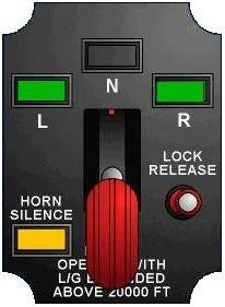
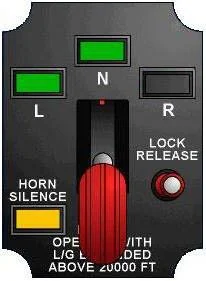
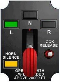
Landing Gear Failure to Extend

Photo: GV Landing Gear Unsafe, from "Landing Gear 101".
The landing gear system on the G450 is pretty much what they had on the G159, the venerable "Gee One" so there is lots of history to this system. Gulfstream has a very nice presentation called "Landing Gear 101" which covers just about every malfunction known to have happened on these landing gear. I've copied most of that below but let me leave you with the bottom line up top:
"There have been many cases where recycling has helped and many cases where it made things worse. Recently this is the trend. For 40 years there have been no cases where an emergency extension made things worse."
In the GIII the original procedure was to recycle. The procedure in the GIV and the airplanes to follow was to leave the gear down and use the emergency extension system. Good enough for me. The procedures are good but there are a few notes that may come in handy should this ever happen to you.
Symptoms
The gear handle is down but one or all three gear are not.
Procedure: Unsafe Landing Gear Indication
[G450 AFM, §03-17-20]
CAUTION: BECAUSE WIRING LOGIC IS DIFFERENT FOR A DOWN-AND-LOCKED GEAR INDICATION, THE LANDING GEAR POSITION INDICATION ON THE LANDING GEAR CONTROL PANEL TAKES PRECEDENCE OVER THAT DISPLAYED ON THE FLIGHT CONTROL SYNOPTIC PAGE.
The 3 GREEN on the synoptic come through the MAU's and can be subject to software issues. The 3 GREEN on the landing gear control panel are hard wired and can be believed.
IF ONE OR MORE LANDING GEAR CONTROL PANEL LIGHTS FAILS TO INDICATE GREEN:
ANN Lights . . . TEST
IF TESTING THE ANNUNCIATOR LIGHTS REVEALS INOPERATIVE BULB(S) AT THE SUSPECT LANDING GEAR POSITION AND REPLACING THE BULB DOES NOT RESOLVE THE PROBLEM:
Landing Gear Failure to Extend Checklist . . . PERFORM
Procedure: Landing Gear Failure to Extend
[G450 AFM, §03-17-30]
If normal operation of the landing gear does not result in its proper extension and locking, alternate extension will be required. If a loss of Left Hydraulic System (L SYS) fluid occurs, the Power Transfer Unit (PTU) will not be available for use.
LDG GEAR CONT Circuit Breaker . . . CHECK / RESET
LDG GEAR CONT; POP, E-4
Landing Gear Handle . . . DOWN
NOTE: Ensure the landing gear handle is DOWN for proper landing gear position indication, and anti-skid braking system operation. Operation of the alternate landing gear extension system is not dependent on the position of the landing gear handle.
EMERG LDG GEAR Handle . . . CHECK
Verify the EMERG LDG GEAR Handle is fully down and seated by applying downward pressure on the handle.
LDG GR DUMP V Switch . . . DEPRESS
Located on the Cockpit Overhead Panel, depressing this switch will not cause the DUMP legend to be illuminated, but will provide an electrical path for the extension control circuit.
There are a series of valves that turn the "down" lines into return lines when the gear handle is up, and the "up" lines into return lines when the gear handle is down. There is a chance that one or more of these valves are stuck so that the particular return line is still providing "up" pressure. This step attempts to move the valve into the correct position using a solenoid.
IF PROPER GEAR POSITION AND INDICATION IS NOT ACHIEVED:
CAUTION: A FULLY CHARGED NITROGEN BOTTLE SYSTEM (3100 PSI AT 70°F / 21°C) IS DESIGNED TO PROVIDE ONLY ONE EXTENSION OF LANDING GEAR.
Airspeed . . . 175 KCAS OR LESS
EMERG LDG GEAR Handle . . . PULL
CAUTION: DO NOT RESET EMER LDG GEAR HANDLE.
LDG GR DUMP V Switch . . . VERIFY DUMP LEGEND ILLUMINATED
CAUTION: DO NOT RESET DUMP VALVE.
Landing Gear Position . . . DOWN / 3 GREEN
CAUTION: IF ONE OR MORE LANDING GEAR FAIL TO EXTEND, SEE SECTION 04-18-20, ABNORMAL GEAR CONDITION - EMERGENCY LANDING.
AFTER LANDING:
CAUTION: LANDING GEAR SAFETY PINS SHALL BE INSTALLED PRIOR TO RESETTING THE DUMP VALVE.
Landing Gear Safety Pins . . . INSTALL
Procedure: Nose Gear Retracted, Both Main Gear Down And Locked
[G450 AFM, §04-18-30]
If contamination of the uplocks due to ice and snow is suspected, consider flying to an area where melting can occur. If fully retracted, attempt to release from uplocks by applying positive ″g″ loading not to exceed 2.5 g’s flaps up. If partially extended but not locked down, perform a normal approach and firmly bump the main wheels on runway in an attempt to shake the nose gear down and locked. Execute go around. Consideration should be given to flying faster than normal in order to increase elevator effectiveness and the nose falling through on touchdown.
LANDING PROCEDURE:
GPWS GND SPLR FLAP ORIDE . . . ON
GPWS Voice Override . . . ON
Touchdown . . . RUNWAY CENTERLINE
Speed Brakes . . . EXTEND AS NECESSARY
Pull the handle slowly to allow adjustments to pitch pressure.
Thrust Reversers . . . USE MAXIMUM (BOTH ENGINES)
This will reduce load on nose.
Wheel Brakes . . . USE MINIMUM
Wheel brake pressure will increase the downward pitch moment
Nose . . . FLY ONTO RUNWAY
Relieve weight with elevator after runway contact.
Brakes . . . AS NECESSARY FOR DIRECTIONAL CONTROL AND STOPPING
Before you begin this, you should consider reviewing the Ground Evacuation Checklist.
One Main Gear And Nose Gear Down And Locked, Opposite Main Gear Retracted
[G450 AFM, §04-18-40]
If fully retracted, attempt to release from uplocks by applying positive “G” loading not to exceed 2.5g with flaps UP (0°). If partially extended, attempt to lock unsafe gear down. Yaw the airplane to apply spanwise air load to force the affected gear outboard; left rudder for left main gear, right rudder for right main gear.
If the flaps are down you can apply 2.0 G's.
LANDING PROCEDURE:
GPWS GND SPLR FLAP ORIDE . . . ON
The checklist doesn't tell you about two problems that will be facing you that can throw you for a loop, figuratively and literally:
When you select 39° flaps the configuration warning horn will start to sound and you will not be able to silence it.
If you are using the autothrottles they will not retard at 50 feet (because they require both main gear WOW) and will be perfectly happy to remain at approach power as you drive down the length of the runway. It is up to you to pull them to idle.
Touchdown . . . SIDE OF RUNWAY WITH SAFE GEAR
NOTE: Ground spoilers and thrust reversers will not be available with one main gear retracted.
Speed Brakes . . . EXTENDED
Brakes . . . AS NECESSARY FOR DIRECTIONAL CONTROL AND STOPPING
NOTE: Nosewheel steering is unavailable in this configuration. Both Main Landing Gear Weight-On-Wheels (WOW) and Combined WOW must be in the GROUND mode to enable steering.
Unsafe Gear . . . RELIEVE WEIGHT WITH AILERONS
Before you begin this, you should consider reviewing the Ground Evacuation Checklist.
One Main Gear Only Down And Locked
[G450 AFM, §04-18-50] If only one main gear is extended, retract gear and perform an all gear up landing. Touchdown on runway centerline. When aft fuselage contacts runway surface, gently lower nose to runway. Immediately shut down both engines with fire handles, select APU Master OFF, and select batteries OFF. Maintain directional control with rudder.
Before you begin this, you should consider reviewing the Ground Evacuation Checklist.
Both Main Gear Retracted, Nose Gear Down And Locked
[G450 AFM, §04-18-60] If unable to extend and lock down main gear, retract nose gear and perform the ALL GEAR UP LANDING checklist. See 03-17-40, Landing Gear Retraction Following Alternate Extension.
Before you begin this, you should consider reviewing the Ground Evacuation Checklist.
All Gear Up Landing Procedure
[G450 AFM, §04-18-70]
NOTE: Do not apply spoilers for this procedure.
Landing Fuel . . . 2000 LBS (907.2 KG) MAX
Airplane . . . DEPRESSURIZE
CABIN PRESS CONTROL . . . MANUAL
TROV . . . FULL OPEN
GPWS / GND SPLR FLAP ORIDE . . . ON
The checklist doesn't tell you about two problems that will be facing you that can throw you for a loop, figuratively and literally:
When you select 39° flaps the configuration warning horn will start to sound and you will not be able to silence it.
If you are using the autothrottles they will not retard at 50 feet (because they require both main gear WOW) and will be perfectly happy to remain at approach power as you drive down the length of the runway. It is up to you to pull them to idle.
Final Approach Configuration . . . FLAPS 39° / VREF
Use final approach speed of VREF or as slow as possible at all planned wheels up landing weights and fly a very shallow approach angle.
Elevator Trim . . . SET TO DEVELOP MAX NOSE UP MOVEMENT
A slight control column push may be required to maintain proper pitch attitude.
Sink Rate . . . TARGET LOW AT TOUCHDOWN
Flap segments are likely to break clean away from the wing at touchdown.
Touchdown . . . RUNWAY CENTERLINE
When aft fuselage contacts runway surface, immediately shut down both engines with FIRE handles.
AFTER TOUCHDOWN:
Directional Control . . . MAINTAIN WITH RUDDER
Pull control column to the full aft position during the remainder of the ground run to maintain a nose high attitude.
Both Engine FIRE Handles . . . PULL
When aft fuselage contacts runway surface, immediately shut down both engines with FIRE handles.
APU MASTER . . . OFF
BATTERIES . . . OFF
WHEN STOPPED:
Passengers/Crew . . . EVACUATE IMMEDIATELY
What you should consider
[Gulfstream's Landing Gear 101]
History
40+ years on the fleet, gear nearly same from GII through G550
2 Nose gear up landings, almost a 3rd (GIV packed with frozen slush, GV mechanical failure of critical part, GII nose strut wiped with Skydrol rag
Main gear has always come down (Aggressive maneuvering, Bounces and Scuffs, Improvised emergency procedures)
Emergency system has always "worked" (Nitrogen released and routed to actuators). Sometimes it was unable to overpower a mechanical problem but neither was 3000 psi hydraulic pressure. In one case where routed to a ruptured actuator.
Landing Gear Basics
NORMAL system
Control is mechanical or electrical
Power is Hydraulic
Indication is electric
EMERGENCY system
Control is mechanical
Power is pneumatic
Indication from normal system
Landing gear handle
2 position: UP/DOWN
Controls a Selector Valve which routes hydraulic power to each landing gear
3 gear operate independently of each other, operating sequence is controlled by mechanical linkage
"Gear Down" indication via independent electrical circuits
Emergency Extension
Mechanical control releases Nitrogen
Nitrogen pressure shifts dump valve, return path to reservoir for up-side hydraulics
Dedicated routing for pressure to each gear
Shuttle valves on actuators for door, uplock, and gear
Shifted by nitrogen
Allow nitrogen to power the actuators open/down
Shuttle valves are common to normal & emergency systems
No sequencing or timing: gear will push door out of the way
Failure Modes
Control (handle or selector valve)
Mechanical: restricted movement or no movement
Electrical: safety solenoid, selector/dump solenoid, or wiring and connections
Hydraulic Power: pump failure or fluid loss
Indication: only 1 switch per gear for "gear down," 2 bulbs per capsule, Ess DC power, loss is possible but not likely
Mechanical Sequencing
Gear Down: doors open, uplocks release, gear extends, doors close
Gear Up: doors open, downlocks release, gear retracts, doors close
Sequencing linkage: lightly loaded mechanical connection to valves, positions valves to control flow to actuators. Bungees are spring-loaded units in the linkage which extend to reposition valves and maintain tension on the mechanical links.
Mechanical sequencing failures: can occur when linkage broken, binding, or rigging out of adjustment. Result is that components do not operate or interfere with each other.
Failure Modes - Sequencing/Hydraulics
"Minor" difference in electrical vs. mechanical control proved to be significant
Solenoid operation causes rapid spool shift
Pressure transients in gear lines: positive (spikes), negative (suction force), transients greatest at end of lines (NLG)
NLG uplock actuator may shift toward open
Sequencing linkage moves door control valve to blocked ports region
NLG "slow to operate" or stays up
Normal Wear
Bushings, Bearings, and Pins
Parts move out of alignment and bind: gear slow to extend or may not lock down
Most prevalent with NLG
Same NLG symptoms as "pressure bumps"
Things to Consider
Cause of the problem (Hydraulic, Electrical, Mechanical)
Recent aircraft maintenance
Recent gear behaviorInflight problems that can't be duplicated on jacks are usually electrical
Slow to operate may be binding, rigging, pressure jumps
No response to selection
Electrical = bad solenoid, wiring, or no power
Mechanical = dump valve shift or leakage
If you get any response to gear selection, the problem is not electrical (GIVX, GV, GVSP)
Recycling
We recycle in the hope things will get better; sometimes they do
There is an equal chance they will get worse; lately they have
There is reluctance to use the emergency system because reset requires maintenance action (40 man-hours, 1 day)
Aircraft with electrical control of gear selection may get a different hydraulic response by recycling; better or worse
Recycle something that's binding; may be freed or may stick in a worse position
If unsure where some gear component is, it makes no sense to recycle
If you know something is out of sequence, it makes no sense to recycle
Gear door OPEN with gear handle UP
Something is out of sequence, but the open door is out of the way
Put handle back down to recycle, door may interfere with gear
If gear goes down but doesn't lock, bungee likely jammed in extended position
Retract gear so door is known to be clear, blow the gear, put handle down for normal indication
For the GV
Recycle once if no response to gear down selection
Recycle once if nose gear doesn't go down but both main gear do
If any gear does not retract after takeoff select gear down and return to the field for landing
Final Thoughts
There have been many cases where recycling has helped and many cases where it made things worse. Recently this is the trend. For 40 years there have been no cases where an emergency extension made things worse.
Landing Gear Failure to Retract

This seemingly minor problem is one of the few things in this airplane that can kill you. If you attempt to raise the gear handle and can't, you may forget to disarm the ground spoilers. But that is exactly what you need to do first. The handle, more than likely, is stuck down because both main landing gear WOW switches failed to go to AIR mode. You will next be confronted with an early level off considering a return to the airport. If you or the autothrottles bring the power levers to idle, all the conditions for deployment of the ground spoilers will have been met. Turn the ground spoilers off immediately!
I've heard from simulator instructors that a common issue here is pilots fixate on the gear handle and forget about the ground spoiler switch. I can see that, so I've adopted the practice of turning the ground spoiler switch off before raising the gear handle. I may never have to rely on this procedure but it doesn't hurt anything during normal operations and it could save me if I ever do have a WOW issue on takeoff.
If the WOW is in GROUND mode I'm not so sure I would want to raise the landing gear and press on. You will have other issues facing you.
See WOW Fails to Shift to AIR Mode After Takeoff in this page.
If the handle moved but the gear did not, you either got a lot of CAS messages about your lack of hydraulics or you didn't. If you did, you have another checklist to jump to.
See: Left Hydraulic System (L SYS) Failure – Loss of Pressure and Fluid.
If the handle moved but the gear did not and you didn't get that stack of CAS messages, you probably left the gear pins in. Here again you have another checklist to visit: Attempted Gear Retraction with Pins Left In in this page. But before you go there, disarm the ground spoilers. To date, the only GV ever lost was because the pilots forgot this step: GV N777TY.
Symptoms
The gear handle may or may not come up, one or all three gear remain down.
Analysis
If the gear handle will not come up the most likely cause is the weight on wheels system has failed to go to AIR mode. If the ground spoilers are armed and the throttles come to idle, the ground spoilers will come up. (And the airplane will come down.)
If the gear handle did come up but the gear did not, you may have a loss of left system fluid.
If the hydraulics are good, you may have left the landing gear downlock pins in.
Of course as complicated as the airplane is, there can be other causes. (See Letters to Eddie, below.)
Procedure
[G450 Aircraft Operating Manual, ¶3-17-10]
WARNING: DO NOT RETARD POWER LEVERS TO IDLE IN FLIGHT. GROUND SPOILERS MAY DEPLOY.
If the landing gear handle will not move:
GND SPLR Switch ... OFF
Autothrottle ... OFF
LOCK RELEASE Button ... PUSH
LDG GEAR Handle ... UP
If landing gear handle moves but landing gear does not:
LDG GEAR CONT CB (POP, E-4) ... CHECK / RESET
Hydraulics Synoptic Page ... SELECT
L SYS Quantity / Pressure ... CHECK
NOTE: If either L SYS quantity or pressure are not indicated, see Left Hydraulic System (L SYS) Failure – Loss of Pressure and Fluid
If landing gear still fails to retract:
Landing Gear Handle ... DOWN
NOTE: The possibility exists that all three (3) gear pins were left in.
Landing Gear Dump Valve Switch ... PRESS AND HOLD FOR THREE (3) SECONDS
The airplane should land for troubleshooting.
Letters to Eddie
Eddie,
You may want to be aware that we got a gear failure to retract on our G450 and it was not hydraulics or pins left in. The gear stayed down and locked even with the handle in the up position. We completed the checklist, burnt off some fuel, landed without incident. What ended up happening was the dump valve failed. So just wanted to let you know this could happen as well :)
We have the habit flow of spoilers off right after gear handle goes up, so that was taken care of...but I like your idea of doing the flow with it first, not second.
I am on a G550 now...but love your site.
Best Regards
Nose Wheel Steering Failure
This airplane does not taxi elegantly without nose wheel steering and if I found myself without it, I would clear the runway and see how it goes. I would never consider taxiing the airplane into a crowded ramp this way. The only time this has happened to me the taxiways were icy and it was an easy decision. I stopped the airplane on the runway and called for a tug.
CAS:
Steer By Wire Fail
Tiller Steering Fail
Rudder Steering Fail
Symptoms
One of the CAS messages above.
Analysis
The Steer By Wire Fail message indicates that both channels of the steering ECU have failed. Cycling the switch off then on reboots it.
The Tiller Steering Fail indicates the tiller RVDT input to the ECU has failed. You should still have nose wheel steering through the rudder pedals.
The Rudder Steering Fail indicates the rudder RVDT input to the ECU has failed. You should still have nose wheel steering through the tiller.
Procedure
[G450 AFM, §3-18-60]
NOTE: On ground only, for the following nose wheel steering messages, if cycling the nose wheel steering power or pedal disconnect switches does not resolve the issue, cycle the STEER BY WIRE circuit breaker (REER, C-8).
If Steer By Wire Fail message is displayed:
NOSE WHEEL STEERING POWER ... OFF, THEN ON
If Steer By Wire Fail message is still displayed:
NOSE WHEEL STEERING POWER ... OFF
Landing:
NOTE: The NWS fails passive to a free-castor mode. Shimmy damping will still be available.
After touchdown, use rudder and differential braking for directional control until reaching a slow taxi speed or stopped.
NOSE WHEEL STEERING POWER ... ON
NOTE: If message extinguishes, expect normal nose wheel steering output.
If Tiller Steering Fail message is displayed:
PEDALS DISC...VERIFY ON (DISC LEGEND EXTINGUISHED)
Rudder Pedal Steering ... UTILIZE
CAUTION: WITH TILLER STEERING FAILED, RUDDER PEDAL AUTHORITY IS INCREASED TO PROVIDE ±16° NOSE WHEEL TRAVEL.
If Rudder Steering Fail message is displayed:
PEDALS DISC... OFF (DISC LEGEND ILLUMINATED)
Tiller Steering ... UTILIZE
After touchdown, use rudder and tiller for directional control until reaching a slow taxi speed or stopped.
PEDALS DISC ...ON (DISC LEGEND EXTINGUISHED)
If Rudder Steering Fail message is still displayed:
PEDALS DISC ... OFF (DISC LEGEND ILLUMINATED)
Weight on Wheels Fails to Shift to AIR Mode After Takeoff
This is one of the few things in this airplane that can kill you so your priority is to immediately remove the threat: disarm the ground spoilers, ensure the throttles do not come to idle, and pull the circuit breakers. Now the threat is gone and you can land.
CAS:
WOW Fault
This is the only amber WOW fault CAS message, but it is a serious one.
Symptoms
You may or may not get the CAS message but you will not be able to raise the landing gear handle.
Analysis
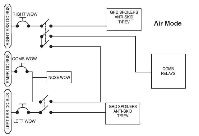
Both main gear WOW are in the ground mode while the combined WOW has figured out that the airplane is higher than 147.5 feet. (See G450 WOW for more about this.)
Procedure
[G450 AFM, §3-18-90]
WARNING: DO NOT RETARD POWER LEVERS TO IDLE IN FLIGHT. GROUND SPOILERS MAY DEPLOY.
GND SPLR OFF/ARMED Switch ... OFF
Your first indication will probably be that the gear handle did not come up and you may fixate on the gear handle and forget the ground spoilers. If you then level off and the autothrottles retard the throttles, the ground spoilers could hurt you.
Autothrottle ... DISCONNECT
Flight Controls Synoptic Page ... CHECK TO DETERMINE WHICH WOW SIGNAL HAS FAILED
NOTE: If Rad Alt is failed, WOW indications will display as invalid (cross-hatched) on Flight Controls synoptic / system pages.
Appropriate WOW CB ... PULL
LEFT WOW: POP, C-1
RIGHT WOW: CPOP, C-1What if the airport you just left is 500 RVR and you need to fly an hour away to get back on the pavement? Following the book procedure the gear will not come up and the airplane will not pressurize. Now what? The book doesn't say this but if you really needed to do this to stay safe, pulling the Combined WOW — POP, C-2 — gets all of the airplane back into the air mode, including the landing gear and pressurization. Note: this is a valid GIV procedure but has been left out of the GV series for some reason. If I just left KEGE and the weather or my weight precluded an emergency return, I would use this technique to allow me to hop over the mountains and get to Denver. But that's just me.
After landing:
Speed Brakes ... EXTEND
WOW CB(s) ... RESET TO REGAIN GROUND MODE
NOTE: Once below 50 knots, WOW will shift to the GROUND mode
This isn't true. As soon as your wheels spin up you will have normal thrust reverser control and wheel brakes. If you forget to reset the circuit breakers, your thrust reversers will be stuck where you left them below 50 knots and you will loose wheel brakes below 8 knots. Therefore, after you touchdown and before you start to come off the reversers, you need to reset those breakers.
Weight on Wheels Fails to Shift to GROUND Mode after Touchdown
The QRH deals with everything important, but you just touched down at 125 knots and the end of the runway is 30 seconds in your immediate future. Maybe you should have a few things memorized. To cover all your bases:
Manually deploy speed brakes.
Stow thrust reversers completely prior to 50 knots.
Turn off anti-skid braking prior to 50 knots.
Turn cabin pressure controller to MANUAL and rotate MAN HOLD to CLIMB
Be prepared to use differential braking as necessary.
CAS:
WOW Fault
Symptoms
You may or may not get the CAS. If you don't, your first indication of this may be that the ground spoilers do not automatically deploy and you get a warning horn with the thrust reversers.
Analysis
Wheel Spin Up. When wheel speed is greater than 47 knots, the Digital Anti-skid Control Unit provides a wheel speed monitor signal to Modular Avionics Units #1 and #2 for communication to applicable circuits of the ground spoilers and thrust reversers for secondary control signals in the event of Weight-On-Wheels (WOW) system failures. So when you touchdown, even with a WOW failure, you will have brakes and thrust reversers. But not for long.
You probably won't get the CAS message until about 50 knots. You might get an ADS Miscompare message. A good copilot may have noticed the WOW still in the air mode when checking the flight control synoptics for good reverser and ground spoiler deployment. In any case, for a left or right main gear WOW, you can expect to lose that side's wheel braking at 47 knots, the ground spoilers to retract, and that side's thrust reversers may refuse to stow. A nose WOW failure will leave you without nosewheel steering. In the case of the combined WOW, the airplane may remain pressurized.
Procedure
[G450 AFM, §3-18-80]
To determine which WOW signal has failed:
Flight Controls Synoptic Page ... SELECT
WOW Indications ... OBSERVE
NOTE: If Rad Alt 1 is failed, WOW indications display invalid (crosshatched) on the pilot’s display. If Rad Alt 2 is failed, WOW indications display invalid (cross-hatched) on the copilot’s display.
If Combined WOW signal has failed:
CABIN PRESSURE CONTROL FAULT / MANUAL ... MANUAL
CABIN PRESSURE CONTROL MAN HOLD. .. ROTATE TO CLIMB
If the Left or Right Main Landing Gear WOW signal has failed:
The ground spoilers, thrust reversers and anti-skid systems receive discrete L or R WOW signals. If the WOW signal is lost, a wheel spinup signal will replace the WOW signal to these systems. Systems operation will rely on wheel spin-up occurring and then will operate normally. Systems operation will cease at a certain point of deceleration, as wheel spin-down occurs.
NOTE: Thrust reversers must be stowed prior to decelerating below 50 knots; otherwise, thrust reversers will not respond to thrust reverser lever movement.
If the Nose Landing Gear WOW signal has failed:
NOTE: Nose wheel steering will not be available.
Differential Braking ... AS NECESSARY
References:
Gulfstream Breakfast Minutes, G350/G450/GV/G500/G550 (ATA 32): Landing Gear Fails to Retract, January 18, 2013
Gulfstream G450 Aircraft Operating Manual, Revision 35, April 30, 2013.
Gulfstream G450 Airplane Flight Manual, Revision 35, April 18, 2013
Gulfstream G450 Maintenance Manual, Revision 18, Dec 12, 2013
Gulfstream G450 Operating Manual Supplement, G-450-OMS-02, Extended Operations (ETOPS) Guide, Revision 2, April 2, 2009
Gulfstream G450 Quick Reference Handbook, GAC-AC-G450-OPS-0003, Revision 34, 18 April 2013
Gulfstream G450 Weight and Balance Manual, Revision 3, March 2008
Salamankas, John, "Landing Gear 101", Gulfstream Presentation