Landing Gear System
- James Albright (a former G450 driver)
Updated: 2008-08-21
The G450 landing gear system is pretty much unchanged from previous generations of Gulfstreams except the mechanical selector switch up front is now a switch, the weight on wheels system has a number of sophisticated check systems, the system that warns you if the gear isn't down is smarter, the brakes are vastly improved, and there have been a lot of little tweaks here and there to insure the gear always comes down.
And it almost always does. (There has been on exception.)
Everything here is from the references shown below, with a few comments in an alternate color.
Landing Gear and Doors
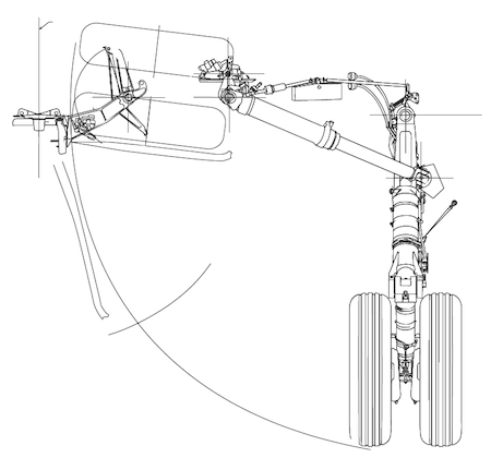
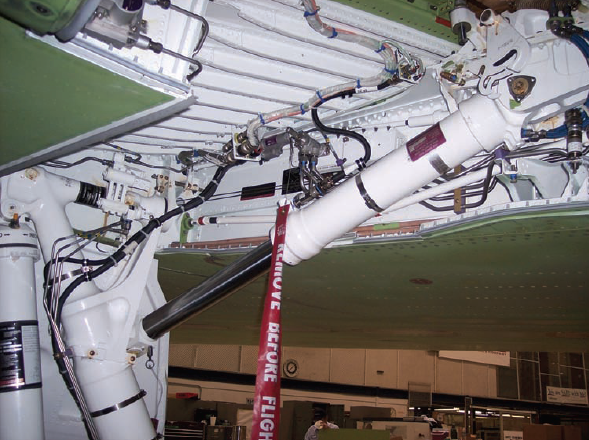
[G450 AOM, § 2A-32-20 ¶1.A.] The major components of each main landing gear assembly are: a landing gear door, a shock strut, a sidebrace actuator/downlock mechanism and an uplock mechanism. Each of the main landing gear assemblies has dual wheels with integrated brakes mounted on an articulated trailing arm attached to the landing gear structural post. The pneumatic/hydraulic shock strut is attached between the wheel end of the articulated trailing arm and the top of the structural post.
[G450 AOM, § 2A-32-20 ¶1.A.] A side brace hydraulic actuator/downlock extends and retracts the main gear. In the extended position, mechanical downlocks prevent gear retraction. The downlocks include mechanical springs loads that maintain the locked position without hydraulic pressure. In gear retraction, hydraulic pressure compresses the springs, displaces the downlocks and allows gear retraction inward into the wheel well in the wing root next to the fuselage keel. An uplock roller mounted on the dual wheel axle assembly engages an uplock hook in the wheel well and rotates to latch the main gear in the uplocked position. The main landing gear door, hinged at the inboard side of the wheel well, closes after the gear retracts and mates with the fairing door panel linked to the outside of the main gear assembly to seal the wheel well.
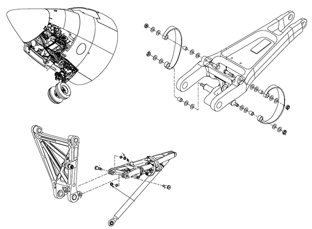
[G450 AOM, § 2A-32-20 ¶1.A.] The nose gear assembly includes steerable dual wheels mounted on a shock strut attached to a trunnion and a hinged two piece truss brace. A drag brace between the truss brace and the shock strut provides additional structural support. The truss brace and trunnion pivot axes allow the hydraulic actuator cylinder to retract the nose gear assembly forward and up and extend the gear aft and down.
[G450 AOM, § 2A-32-20 ¶1.A.] When the nose gear is fully extended, the forward and aft sections of the truss brace move over center to lock the nose gear down. A downlock hydraulic cylinder extends an actuating arm placing the truss brace in the over center position. Springs are also incorporated in the over center downlock to maintain the over center lock in the event of hydraulic failure. When the nose gear retracts, the downlock actuator arm moves aft, allowing the forward and aft portions of the truss brace to fold at the hinge point. As the nose gear reaches the fully retracted position, a roller attached to the dual wheel axle assembly pushes aside a spring latch and engages an uplock hook, with the spring latch then falling into place securing the roller into the uplock hook. A hydraulically actuated pushrod then rotates the uplock hook upward to provide positive nose gear latching.
[G450 AOM, § 2A-32-20 ¶1.A.] Two symmetrical nose wheel doors, hinged on the outside of the nose wheel well are mechanically linked together. Timing valves integrated into the extension/retraction cycle operate the hydraulic door actuating cylinder in the correct sequence. When the nose gear is retracted and seated in the uplock hook, the doors close to cover the forward wheel well, with the fairing panel linked to the rear of the nose gear drag brace enclosing the aft portion of the wheel well.
[G450 AOM, § 2A-32-20 ¶1.A.] Indication of landing gear position is provided to the flight crew through lights on the landing gear control panel, an aural warning horn, and by messages on the CAS in the event of malfunction.
Landing Gear Doors
[G450 AOM, § 2A-32-20 ¶2.A.] Each main landing gear wheel well is enclosed by a single door in conjunction with a fairing panel linked to the outside of the gear strut. The nose gear wheel well is enclosed by two symmetrical curved doors and a fairing panel linked to the aft side of the nose gear. When the landing gear are fully extended, the gear doors close to reduce drag and air noise. All gear door movement is sequenced by mechanical linkages operating hydraulic actuators to coordinate actuation with landing gear extension and retraction.
Procedures exist to open and close the doors on the ground in order to accomplish maintenance tasks. Hydraulic power from the Auxiliary (AUX) system and operation of a ground service valve, located adjacent to the nose wheel well, allow movement of the gear doors by pressurizing the landing gear system on the ground.
Shock Struts
[G450 AOM, § 2A-32-20 ¶2.B.] Standard oleo-pneumatic (gaseous nitrogen and hydraulic fluid) shock struts are incorporated into each gear assembly. The shock struts consist of a movable steel piston within a cylinder containing hydraulic fluid pressurized with gaseous nitrogen. O-ring seals maintain strut pressure and allow the movement of the piston. The struts absorb the shock of landing, and provide damping during taxi, takeoff and landing rollout. An air/oil filler valve is provided at the top of each strut for servicing. During normal operations, approximately three to five inches of piston chrome is exposed at the bottom of each main landing gear strut, depending on aircraft gross weight and outside air temperature. A placard attached to upper portion of the landing gear strut indicates the correct extension for ambient conditions.
Main Landing Gear Sidebrace Actuator / Downlock Mechanism
[G450 AOM, § 2A-32-20 ¶2.C.(1)] The sidebrace hydraulic piston and actuator arm extends the main landing gear outboard and down from the wheel well and locks the landing gear in the down position using internal locking keys located in the lower end of actuator cylinder. The keys slide into annular slots when the sidebrace actuator reaches full extension. A lock ram positioned by down hydraulic pressure and a spring maintain the keys in the slots preventing any further actuator movement. Spring pressure is necessary to maintain the keys in the locked position without hydraulic pressure. The movement of the keys into the slots also provides the input for the downlock microswitch that provides the cockpit indication that the gear is down and locked. When the gear is selected up, hydraulic pressure is ported to the other side of the lock ram, displacing the keys from the slots and overriding spring pressure, allowing the actuator to move in the retract direction. The sidebrace actuators have provisions for inserting ground lock pins to maintain the main landing gear in the extended position during ground operations.
The sidebrace pushes the main landing gear into the down position and pulls it to the up position. The downlock is inside the sidebrace actuator cylinder. In the down position, keys move to allow the downlock electrical signal and prevent strut compression. The keys are held in place by springs and can only be moved with hydraulic pressure. Theoretically, the main landing gear will not retract without hydraulic pressure.
Nose Landing Gear Extend / Retract Actuator, Nose Landing Gear Downlock
[G450 AOM, § 2A-32-20 ¶2.C.(2)] The nose gear actuator pulls the nose gear aft and down to the extended position. One end of the actuator is attached to the aft structural wall of the nose wheel well. The other end is attached to the hinged nose gear trunnion that pivots aft into the extended position.
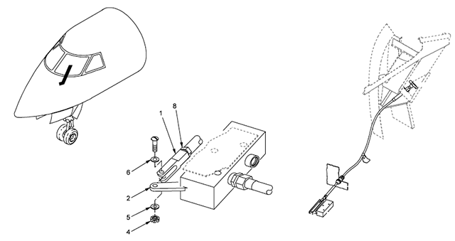
[G450 AOM, § 2A-32-20 ¶2.C.(3)] Nose gear downlock engagement is provided by the over center position of the hinged two part truss brace with integrated downlock actuator and spring. The forward and aft sections of the truss brace unfold as the nose gear extends. As the truss brace unfolds, it forces open the “C” shaped suitcase springs. When the nose gear is fully extended, a hydraulic downlock actuator and linkage pulls the truss brace slightly over center at the hinge point. The truss brace hinge is also held in the over center position by the energy of the “C” shaped suitcase springs that close slightly in the over center position. The springs are necessary to maintain the nose gear in the downlocked position without hydraulic pressure. Once locked into the over center position, hydraulic pressure on the retract side of the downlock actuator is required to push the truss brace past the over center position and overcome spring pressure. The truss brace hinge has a provision for inserting a down lock pin to secure the nose gear in the extended position.
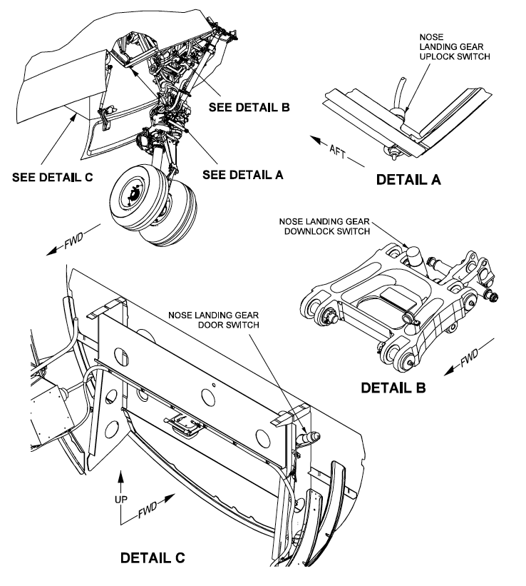
[G450 AOM, § 2A-32-20 ¶2.C.(4)]The downlock microswitch on the nose gear is located on the truss brace. As the truss brace unfolds to the over center position the contact on the nose gear microswitch is depressed sending a downlocked signal to the landing gear control panel.
It takes hydraulic pressure to force the nose gear into the down position and the truss brace overcenter. Sitting on the ground without hydraulic pressure, only the "suitcase" spring ensures the truss brace continues to be overcenter. It could easily move if jostled during towing, hence the need to insert the downlock pins whenever the airplane is towed.
Landing Gear Control
Landing Gear Selector Handle
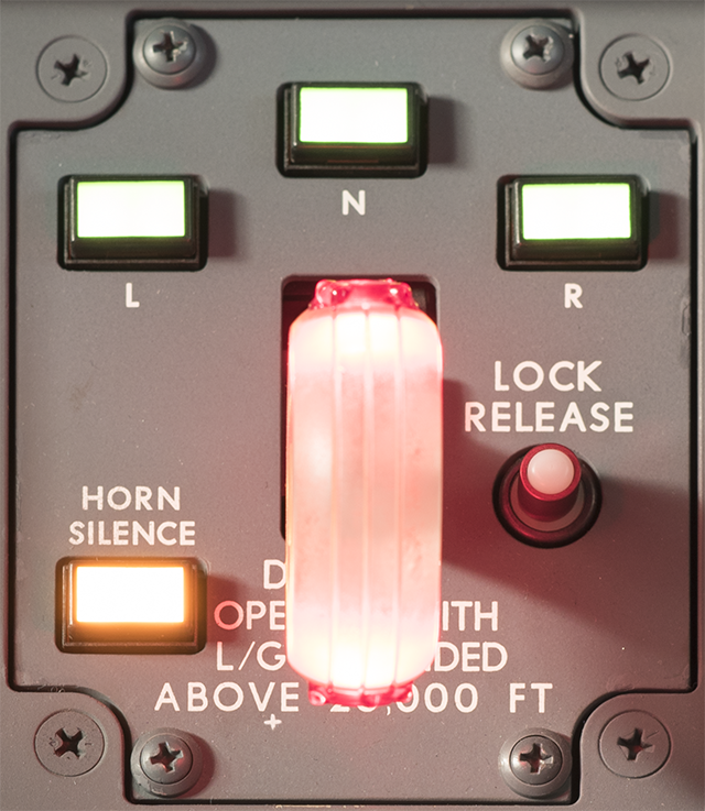
[G450 AOM, § 2A-32-30 ¶2.A.] The landing gear control panel contains the gear lever, position and warning indicators and safety features. Landing gear position and warning lights on the panel are powered by the Emergency DC bus and may be dimmed and tested with switches on the cockpit side consoles.
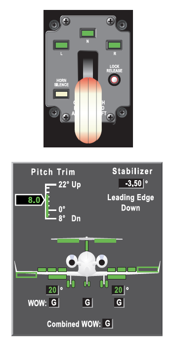
Landing Gear Lever: The landing gear lever is selected into either the UP or DOWN detents on the control panel. To move the lever from one selection to the other, the lever must first be moved to the left to clear the detent. When the lever is moved to a detent an electrical contact is made with the detent switch and transmitted to the extend or retract solenoid on the landing gear hydraulic selector/dump valve in the main wheel well. The solenoid commands the selector valve to route left system pressure to the extend or retract sides of actuators for the landing gear and doors. Lever position has no effect on operation of the emergency landing gear extension system, but the position of the lever is integral to a correct landing gear position indication.
Ground Safety Lock and LOCK RELEASE Button: On the ground with weight on the aircraft wheels (WOW switches on both main landing gear compressed), the landing gear lever is blocked from movement out of the DOWN detent by a solenoid actuated pin. The pin prevents inadvertent retraction of the landing gear due to unintentional movement of the landing gear lever. If the blocking solenoid or WOW switches malfunction during takeoff in the transition to the weight off wheels mode, preventing movement of the landing gear lever to the UP position, pressing the LOCK RELEASE button will manually move the blocking pin clear of the landing gear lever.
Down and Locked Lights: Three green light modules, one for each landing gear, are installed above the landing gear lever. Each light is an independent circuit, illuminating only when the associated gear downlock switch contact is closed.
Gear Warning Horn and HORN SILENCE Switchlight: If the landing gear are not down and locked during flight conditions associated with landing, a warning horn will sound, alerting the crew that the landing gear is not in the correct position. The gear warning horn tone is generated by the Monitor and Warning System (MWS) and annunciated over the cockpit overhead speakers.
The landing gear control and position switches are connected to the Modular Avionics Units (MAUs) through Input / Output (I/O) modules. The modules report switch status to the MWS that generates Crew Alerting System (CAS) messages that accompany the illumination of the red light in the gear control lever.
When you move the landing gear handle, you are sending an electrical signal to the landing gear hydraulic control valve to send hydraulic pressure to the landing gear door control valves.
Landing Gear Hydraulic Control (Selector/Dump) Valve
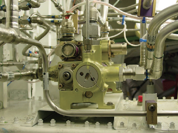
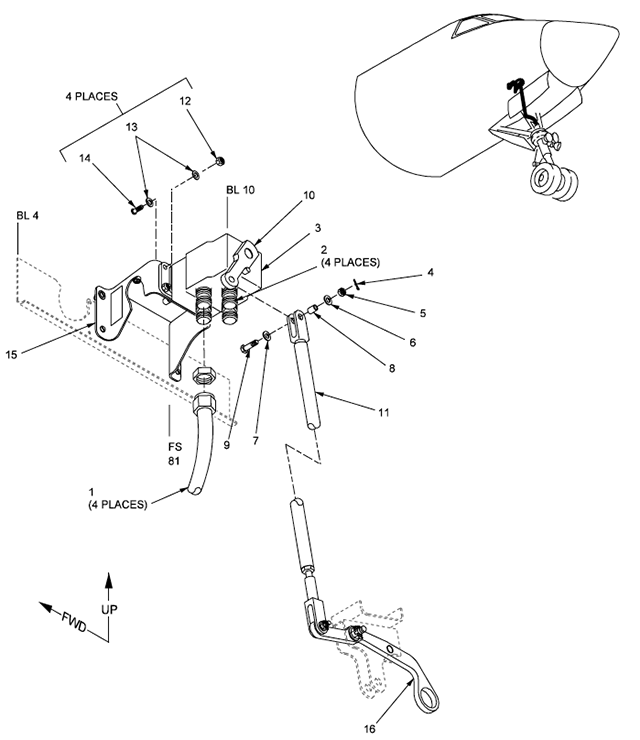
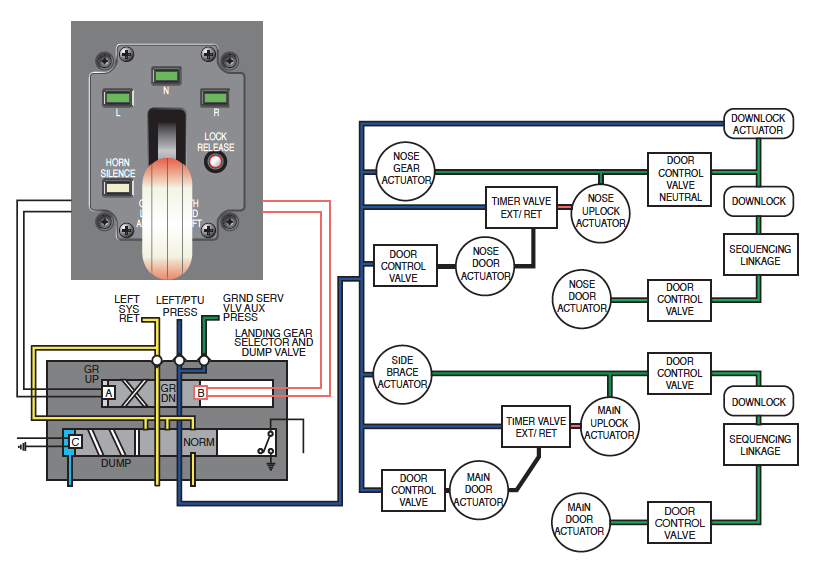
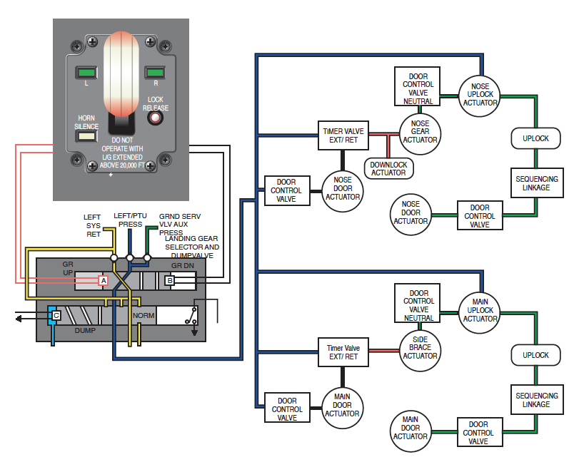
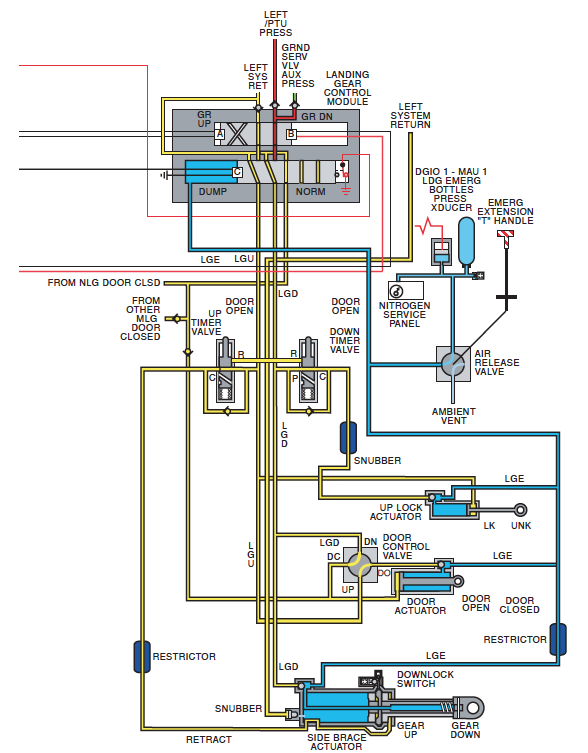
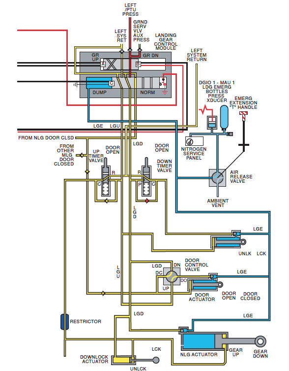
[G450 MM, § 32-30-03 ¶1.A.] The hydraulic control valve (selector / dump valve) contains two electrically controlled valves. The selector valve controls the normal landing gear extension and retraction. The dump valve controls the emergency extension.
[G450 MM, § 32-30-03 ¶3.A.] The selector valve portion of the control valve ports hydraulic fluid to raise and lower the landing gear by receiving electrical signals from the landing gear handle in the cockpit. The dump valve portion of the control valve is actuated into the emergency dump position by pneumatic pressure and is reset to the normal position by solenoid actuation.
This is just like the mechanical valve you had in the GIV, but instead of a cable from the gear handle to the valve you have electrons which move a solenoid. In earlier Gulfstreams the valve was underneath the cockpit and the hydraulic lines traveled aft. In the GV and later, the valve is in the wheel well.
When electrically activated by the cockpit landing gear handle, the landing gear hydraulic control valve sends hydraulic pressure to the landing gear door control valves to begin the extension or retraction sequence.
Landing Gear Door Control Valves (Nose)
[G450 MM, § 32-36-00 ¶3.A.] The door control valve is positioned by a mechanical linkage connected to the nose landing gear uplock latch and to the nose landing gear. This valve directs gear up or gear down pressure to open or close the nose landing gear doors.
When the landing gear handle is placed in the up position, hydraulic pressure is routed to the nose gear door control valve, the uplock actuator, and the retract timer. The door control valve routes hydraulic pressure to the door actuator, moving the doors towards the open position. As the doors approach the nearly open position, a mechanical linkage actuates the retract timer valve which initiates the landing gear retraction. When the uplock hook is approaching the fully closed position, a mechanical linkage actuates the door control valve, causing hydraulic pressure to close the nose gear doors.
When the landing gear handle is placed in the down position, hydraulic pressure is routed to the nose landing gear actuator, door control valve, downlock actuator and uplock timer. The landing gear is initially prevented from moving by a spring on the uplock hook. The door control valve opens the nose gear doors. As the doors approach the nearly open position, a mechanical linkage actuates the uplock which initiates the landing gear extension. When the actuator approaches the fully extended position, a mechanical linkage actuates the door control valve to close the nose gear doors.
Landing Gear Door Control Valves (Main)
[G450 MM, § 32-32-00 ¶3.A.] The door control valve is positioned by the main landing gear sequencing linkage during extension and retraction. The valve controls hydraulic pressure to the door actuator. The door control valves have three positions: door open, neutral and door close. The neutral position ensures the door remains in position, while the main landing gear swings.
When the landing gear handle is placed in the up position, hydraulic pressure is routed to the uplock actuators, retract timer valves and door control valves. Hydraulic pressure is routed through the door control valve to open the main gear doors. Once the doors are open, main landing gear control sequencing initiates retraction. As the landing gear reaches full retracted position, the uplock roller contacts the uplock hook and the uplock actuator locks the landing gear in the up position and activates the door sequencing linkage. The door sequencing linkage repositions the door control valve, allowing the doors to close.
When the landing gear handle is placed in the down position, hydraulic pressure is ported to the side brace actuators, door control valves and the uplock timer valves. Hydraulic pressure is ported through the door control valve to the open port of the door actuator, allowing the doors to open. Once the doors are open, main landing gear control sequencing initiates extension. When the landing gear is extended, the door sequencing linkage repositions the door control valve, allowing the doors to close.
Timer Valves
[G450 MM, § 32-31-00 ¶1.A.] Main landing gear sequencing consists of uplock and retract timers. As the main landing gear door reaches the open position, the timers (valves) allow extend or retract hydraulic pressure to move the main landing gear to the commanded position.
[G450 MM, § 32-31-00 ¶3.A.] The uplock timer is mechanically operated by door movement at extension. The timer routes hydraulic pressure to actuate the uplock actuators to the unlock position. This allows the main landing gear to extend and downlock.
[G450 MM, § 32-31-00 ¶3.B.] The retract timer is mechanically operated by door movement at retraction. The timer routes hydraulic pressure to the retract side of the side brace actuator. This releases the internal downlock and retracts the main landing gear.
Throughout the various manuals you will see references to timers, valves, sequencers, and any combination of those three. They all refer to mechanical valves which direct hydraulic pressure someplace based on mechanical inputs from someplace else. The uplock timer, for example, holds hydraulic pressure in check until a mechanical arm from the gear door actuates the valve to let it know the door is open and it is okay to send pressure to the uplocks which allow the gear to extend. There are no electrons involved.
Landing Gear Uplocks and Downlocks
Main and Nose Gear Uplock Mechanisms
[G450 AOM, § 2A-32-20 ¶2.D.] : The uplock mechanisms of the main and nose landing gear operate in an identical manner, although the components are shaped somewhat differently due to the direction of movement of the nose and main landing gear in the extension/retraction cycle. Operation of the main gear uplocks is described as typical of all landing gear installations.
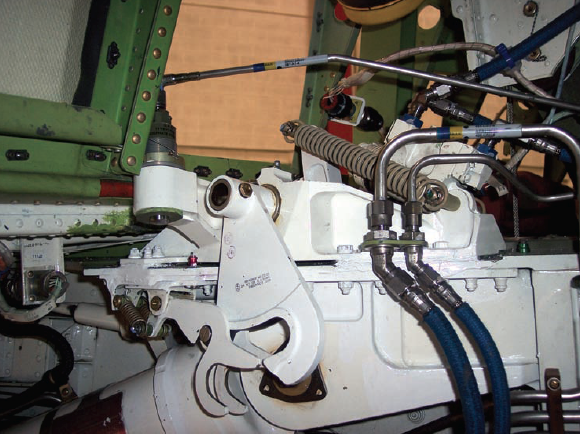
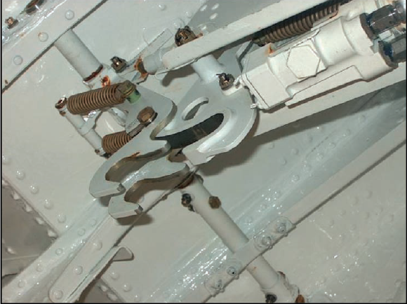
When the main landing gear is fully retracted into the wheel well, the gear is locked into position by a hook and latch that engage an uplock roller mounted on the front of the dual wheel axle housing. The uplock hook and latch mechanism is mounted on the interior forward side of the wheel well. The uplock hook is mechanically positioned by the uplock roller on the landing gear and the uplock latch is positioned by dual springs. (The uplock hook also has dual springs that will maintain the hook in the locked position in event of hydraulic failure.) The integrated latch assembly mechanically blocks movement of the uplock hook until the latch is moved aside by the gear uplock roller as the gear reaches the retracted position. When the latch is moved by the gear uplock roller from the position blocking movement of the uplock hook, the uplock roller enters the concave portion of the uplock hook as the hook pivots into a cradling position. Spring tension on the latch drops the latch into position behind the uplock roller, securing the uplock roller in the uplock hook. The action of the spring held latch counteracts any tendency for the uplock roller to rebound out of the uplock hook and retains the uplock roller in the grasp of the uplock hook after system hydraulic pressure is released.
The uplock mechanisms are only under hydraulic pressure during extension once the landing gear doors are down, or during retraction once the landing gear have reached the up position. The uplock can be moved by hand when the airplane is on the ground. If an uplock is in the up position on the ground, it will remain so during the retraction sequence and will prevent the landing gear from reach its full up position. In all my years in Gulfstreams I've never seen this and have never heard of it happening to anyone but the manual does caution us to look for this during the exterior preflight and gives us the procedure to open the uplock. (Install the door control valve pin and activate the ground service valve.)
Main Landing Gear Sidebrace Actuator / Downlock Mechanism
[G450 AOM, § 2A-32-20 ¶2.C.(1)] The sidebrace hydraulic piston and actuator arm extends the main landing gear outboard and down from the wheel well and locks the landing gear in the down position using internal locking keys located in the lower end of actuator cylinder. The keys slide into annular slots when the sidebrace actuator reaches full extension. A lock ram positioned by down hydraulic pressure and a spring maintain the keys in the slots preventing any further actuator movement. Spring pressure is necessary to maintain the keys in the locked position without hydraulic pressure. The movement of the keys into the slots also provides the input for the downlock microswitch that provides the cockpit indication that the gear is down and locked. When the gear is selected up, hydraulic pressure is ported to the other side of the lock ram, displacing the keys from the slots and overriding spring pressure, allowing the actuator to move in the retract direction. The sidebrace actuators have provisions for inserting ground lock pins to maintain the main landing gear in the extended position during ground operations.
The sidebrace pushes the main landing gear into the down position and pulls it to the up position. The downlock is inside the sidebrace actuator cylinder. In the down position, keys move to allow the downlock electrical signal and prevent strut compression. The keys are held in place by springs and can only be moved with hydraulic pressure. Theoretically, the main landing gear will not retract without hydraulic pressure.
Nose Landing Gear Extend / Retract Actuator, Nose Landing Gear Downlock
[G450 AOM, § 2A-32-20 ¶2.C.(2)] The nose gear actuator pulls the nose gear aft and down to the extended position. One end of the actuator is attached to the aft structural wall of the nose wheel well. The other end is attached to the hinged nose gear trunnion that pivots aft into the extended position.
[G450 AOM, § 2A-32-20 ¶2.C.(3)] Nose gear downlock engagement is provided by the over center position of the hinged two part truss brace with integrated downlock actuator and spring. The forward and aft sections of the truss brace unfold as the nose gear extends. As the truss brace unfolds, it forces open the “C” shaped suitcase springs. When the nose gear is fully extended, a hydraulic downlock actuator and linkage pulls the truss brace slightly over center at the hinge point. The truss brace hinge is also held in the over center position by the energy of the “C” shaped suitcase springs that close slightly in the over center position. The springs are necessary to maintain the nose gear in the downlocked position without hydraulic pressure. Once locked into the over center position, hydraulic pressure on the retract side of the downlock actuator is required to push the truss brace past the over center position and overcome spring pressure. The truss brace hinge has a provision for inserting a down lock pin to secure the nose gear in the extended position.
The overcenter truss "pops" into place with quite a bit of force and requires quite a bit of force to "unpop" to allow retraction. I took a video of it (retraction): Nose gear retraction (extension): Nose gear extension It still isn't a lot that is keeping the nose gear down when you consider the weight of the aircraft. You should never move the airplane without hydraulic pressure on the nose gear or the downlock pin installed.
[G450 AOM, § 2A-32-20 ¶2.C.(4)]The downlock microswitch on the nose gear is located on the truss brace. As the truss brace unfolds to the over center position the contact on the nose gear microswitch is depressed sending a downlocked signal to the landing gear control panel.
It takes hydraulic pressure to force the nose gear into the down position and the truss brace overcenter. Sitting on the ground without hydraulic pressure, only the "suitcase" spring ensures the truss brace continues to be overcenter. It could easily move if jostled during towing, hence the need to insert the downlock pins whenever the airplane is towed.
Landing Position and Warning Indication
[G450 MM, § 32-61-03 ¶4.A.] The landing gear selector panel contains three annunciators (left, right and nose landing gear). They come on when the respective landing gear is in the down and locked position. A red annunciator light in the landing gear control handle comes on whenever there is a disagreement between the handle position and the position of the landing gear. During landing gear retraction, the light in the handle remains on until each landing gear is fully up and locked with landing gear doors closed. During landing gear extension, the light remains on until all three landing gear are down and locked.
[G450 MM, § 32-60-00 ¶1.A.] The downlock switches are located on the nose landing gear downlock brace or main landing gear side brace actuator. The uplock switches are located on the nose landing gear fairing door frame and main landing gear fairing door frame.
There is a single switch in each gear to indicate the gear is up and a single switch in each gear to indicate the gear is down. A green light in the landing gear handle indicates all three are down and locked. With the gear handle in the down position, a red light indicates not all three gear are down and locked. Each gear door has a switch indicating it is closed. With the gear handle in the up position, a red light means not all three gear doors are up and locked.
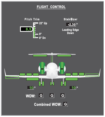
[G450 MM, § 32-60-00 ¶4.A.] Landing gear position and system operation are presented graphically on the Flight Controls synoptic page. When the landing gear are down and locked, the wheels and shock struts of each landing gear are shown in green. When the landing gear are in transit, the struts are shown in magenta. When the landing gear are in the up and locked position, they are not depicted on the display. If any (or all) of the landing gear are in disagreement with the position of the landing gear control handle, the malfunctioning landing gear(s) is shown in amber.
There was a time in the GV when the synoptic was considered more reliable than the lights in the landing gear selector panel. Those days are over, and in at least the G450, the lights take priority. In some other aircraft there were different microswitches for the gear handle, the three green lights, the synoptics, and even for the gear warning horn. For us, each indicator relies on the very same microswitches. We use the lights in the gear selector panel for the overall status, and the synoptics for further definition. With the gear handle up and a red light, for example, the red light tells us a door is not closed. The synoptic tells us which door.
Landing Gear Weight on Wheels System
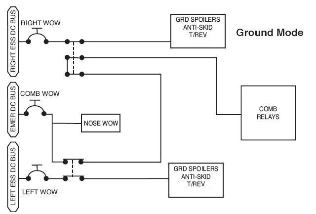
Figure: G450 Weight on Wheels Schematic, from G450 AOM, §2A-32-00, figure 12.
There are two undeniable truths when it comes to any GV series airplane, including the G450:
The ground spoilers are your friends during an aborted takeoff or during landing, but they can kill you if the weight on wheels system malfunctions.
The combined weight on wheels system will not prevent #1 from happening, but it will warn you when the ground spoilers have become your enemy.
The Weight on Wheels system introduced with the GV is a far more robust system than found on earlier Gulfstreams — the nutcracker system — but it shares a few of the vulnerabilities. Fortunately the system now checks itself for faults and will alert you when the system itself might be providing false information.
Main Landing Gear WOW
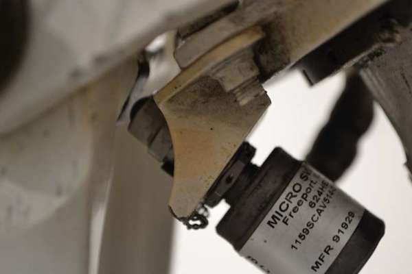
[G450 AOM, §2A-32-30 ¶2.D.] The Weight-On-Wheels (WOW) switch system provides in-air or on-ground sensing for aircraft components that operate in specific regimes. Sensing is provided by three switches installed on the aircraft landing gear: one on each main gear and one on the nose gear. The switches are hermetically sealed and are equipped with gold contacts for reliability. The main landing gear switches are positioned on the side of the shock struts and are closed when the shock strut torque arm rotates when the aircraft weight compresses the switch arms.
The main landing gear WOW ride on irregularly shaped cams and are in the "contact mode," that is, you will not see a gap between the roller and the cam, until the weight is completely off the wheels. In the ground mode, the cam is larger, compressing the switch. In the air mode the cam is smaller, allowing the switch to extend. Why is this important? If the switch is compressed by debris or a maintenance spacer, the WOW tell the ground spoilers the airplane is on the ground when it isn't. The only time you, the pilot, ever see the main gear WOW is in the ground mode.
Here's a look at the thing with the airplane on jacks and the strut compressing: Main Gear WOW video.
See GV N777TY for the only GV series hull loss, a victim of this very problem.
Nose Landing Gear WOW
[G450 AOM, §2A-32-30 ¶2.D.] The nose gear switch is wired differently, with the switch arms are closed in the air and open when the aircraft is on the ground - wiring logic is reversed to provide a signal compatible with the switches on the main landing gear.
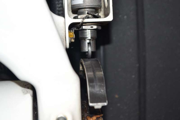
The nose landing gear WOW is simply a microswitch that is either compressed (air mode) or not (ground mode). During preflight there should be a gap. In the G450 the switch is mounted to one side and the wire holding the steering link safety pin can get lodged into the gap, telling the airplane the nose is in the air when it isn't. That could prevent nosewheel steering.
Combined WOW
[G450 MM, §32-62-00, ¶4.A.] The two main landing gear WOW switches are configured to provide left main landing gear WOW, right main landing gear WOW and combined left and right main landing gear WOW signals. One pole within each main landing gear WOW switch is used for the exclusive left WOW or right WOW signal. The combined WOW signals are derived from a series connection through one pole of the left landing gear switch and two poles of the right landing gear switch.
What is the combined WOW? It is just a few lengths of wire from each main landing gear WOW to a series of relays on their way to two MAUs. These relays do control a few things, but these are mostly little things, like letting your cockpit clocks know when to start counting flight time. The most important functions of the combined WOW all happen via the MAUs.
Combined WOW and the Ground Spoilers
Early Gulfstreams had basically the same ground spoiler system as found in the current GV series. Specifically, if the weight on wheels system is somehow fooled into thinking it is on the ground and the throttles are brought to idle, the ground spoilers go up and the airplane comes crashing down.
The GV series introduced the Combined WOW system and led some Gulfstream pilots into thinking it was a safety system to prevent inadvertent ground spoiler deployment. In fact, one of the major training vendors was teaching that very principle.
The Combined WOW has nothing to do with the ground spoilers. Nothing.
The GV series does have a system that warns the pilots if any of the WOW systems appears to be lying. If, for example, the main gear WOW signal the air mode when the airspeed is less than 50 knots, the Master Warning system will notify the pilot with a blue WOW FAULT CAS message. If, for another example, the main gear WOW signal the ground mode when the radio altitude is greater than 147.5 feet, an amber WOW FAULT CAS message is generated.
Note that this system does not prevent the ground spoilers from activating.
Operation
[G450 AOM, § 2A-32-30 ¶2.D.] Each WOW switch has dedicated control authority over designated system operations. Control is exercised by a relay associated with each switch. The relays have multiple internal pole dual air / ground contacts to provide air / ground sensing to the designated systems.
The Main Gear WOW have dedicated signal outputs to:
On-side brake control and indication
On-side engine thrust reverser
Ground spoilers
Combined WOW (through MAUs #1 and #2)
The Right Main WOW also has dedicated signal outputs to the ground service bus. The Left Main WOW also has dedicated signal outputs to the left bus power control unit to provide for power up and ground self test.
The Nose Wheel WOW has dedicated signal outputs to the nose wheel steering system and the aux hydraulic pump.
[G450 AOM, § 2A-32-30 ¶2.D.] Additional circuits of the main landing gear WOW switches signals are used in series control authority for other systems that require additional confirmation of aircraft ground / air state for operation. This additional switch signal is termed Combined WOW. The Combined WOW signal is distributed to a wide range of aircraft system relays to provide air / ground sense for correct operational modes. The Combined WOW signal is provided by a single wire connection that furnishes a 28v essential DC current whenever both main landing gear WOW switches indicate that the aircraft is on the ground. Only a positive indication of the on-the-ground state is necessary, since the using system relays are normally loaded to the in-the-air position - an electrical signal is required to position the relays to the on-the-ground state.
Fault Warning
[G450 AOM, § 2A-32-30 ¶2.D.] Failures of the WOW system will result in inoperative and/or abnormal operation of aircraft systems, depending upon whether the WOW system fails to the ground or flight mode. Blue WOW FAULT CAS messages are generated by the Master Warning System when the Air Data System senses an airspeed of less than 50 knots and any WOW switch is in AIR mode or when radio altitude is greater than 147.5 feet and any WOW switch is in the GND mode. An Amber WOW FAULT message is generated whenever Air Data System airspeed is greater than 60 knots with radio altitude more than 147.5 feet and both main landing gear WOW switches indicate GND mode.
Only one main gear WOW to ground mode is needed for on-side brakes and thrust reversers. Both main gear WOW must be in ground mode to provide ground spoilers and "on the ground" signals to the rest of the airplane through the combined WOW system. If either main gear WOW is in the air mode, the combined WOW thinks it is in the air. The warning system will not save you from an error in the WOW switches, but it will warn you if any WOW switch disagrees with IRS and radio altimeter indications.
Ground Spoiler Techniques
These techniques are not stipulated by any source but I believe can be life savers. Think about them, please:
After takeoff disarm the ground spoilers then raise the gear. If you aren't in this habit and one day the WOW fails to shift to the air mode after takeoff, the gear handle will not come up and you will be tempted to level off to return for landing. Will you have the presence of mind to disarm the ground spoilers at this point if you hadn't already? If the pilot or autothrottles come back to idle, you may be landing sooner than you expected.
More about this: WOW Fails to Shift to Air Mode After Takeoff.
Before you arm the ground spoilers after extending the landing gear, count the three green lights as you have from day one flying retractable gear airplanes but then count the WOW indications, all four of them. Call it out: "Three green, four in the air, ground spoilers armed." What if you don't see "four in the air" at that point? Do not arm the ground spoilers. Just to be safe, pull the ground spoiler circuit breakers.
Landing Gear Extension and Retraction
[G450 AOM, § 2A-32-30] Landing gear extension and retraction is controlled with the landing gear lever on the copilot side of the center instrument panel. The landing gear lever is electrically connected to the extend and retract solenoids on the landing gear selector/dump valve mounted in the main wheel well. Moving the landing gear handle into the extend or retract detent electrically signals the extend/retract solenoid to position the selector/dump valve to route left system hydraulic pressure to the extend or retract side of actuators for the main and nose gear and doors. If left system pressure is not available, but hydraulic lines and fluid quantity are intact, the Power Transfer Unit (PTU) can provide pressure to operate the landing gear. If no hydraulic pressure is available, but system lines remain intact, the landing gear may be lowered by pressurizing the lines with nitrogen gas stored in a emergency bottle located in the nose wheel well. The emergency extension system may only be used once and cannot retract the landing gear.
Extension Sequence
[G450 MM, § 32-00-00 ¶4.A.] When the landing gear handle is placed in the down position, the landing gear selector / dump valve is energized, porting pressure to the nose landing gear actuator, downlock actuator, side brace actuators, door control valves and uplock timers. The uplock hook is spring-loaded in the locked position, preventing landing gear movement. The door control valves route pressure to the door actuators for door opening. When the doors are nearly open, a mechanical linkage actuates the uplock timers routing pressure to the uplock actuators for unlocking the landing gear. The nose landing gear and side brace actuators move to the extended position. Initial movement of the uplock actuators also positions the door control valves in neutral, preventing the door actuators from moving. When the nose landing gear and side brace actuators are almost fully extended, mechanical linkage positions the door control valves to route pressure to the door actuators for door closing.
[G450 MM, § 32-00-00 ¶4.A.] When the nose landing gear reaches the fully extended position, the downlock linkage is forced overcenter by the downlock actuator. As the downlock linkage is locked in the extended position, the downlock microswitch is actuated, sending a nose landing gear down and locked indication. When the main landing gear reaches the fully extended position, the side brace actuator is internally locked and the main landing gear is locked down actuating the downlock microswitch, sending a main landing gear down and locked indication.
[G450 MM, § 32-00-00 ¶4.A.] After the landing gear has extended, the landing gear components are positioned as follows:
Nose landing gear and side brace actuators are pressurized and locked in the extended position
Doors are closed with door actuators pressurized in the fully extended position
Landing gear uplock actuators are unpressurized in the fully retracted position
Uplock timers? An uplock timer is simply a hydraulic valve that waits for input from a mechanical linkage.
[G450 AOM, § 2A-32-30 ¶2.B.(1)] Sequencing:
Landing gear lever is placed in UP position
Red light in landing gear lever handle is illuminated
Landing gear selector/dump valve is moved to RETRACT position
Hydraulic pressure is routed to OPEN side of landing gear door actuators
Landing gear doors open
The timer valves route hydraulic pressure to the RETRACT side of the main landing gear sidebrace actuators, unlocking the internal downlock keys, and to the nose gear actuator and release the nose gear downlock actuator
The nose gear downlock actuator unlocks
Three green DOWN AND LOCKED lights on landing gear control panel are extinguished
Landing gear retracts and locks into uplock hooks and compress uplock switches
Hydraulic pressure is routed to CLOSE side of landing gear door actuators
Landing gear doors close and compress door close switches
Red light in landing gear lever handle is extinguished
Retraction Sequence
[G450 MM, § 32-00-00 ¶4.A.] When the landing gear handle is placed to the up position, the landing gear selector / dump valve is electrically energized, porting left hydraulic system pressure to the door control valves, uplock actuators and retract timers. The door control valves route pressure to the door actuators, opening the doors. When the doors are nearly open, a mechanical linkage actuates the retract timers, routing pressure to unlock the landing gear and pressurize the retract ports of the side brace actuator and the nose landing gear actuator. The nose landing gear downlock actuator forces the downlock linkage out of the overcenter condition, allowing the nose landing gear to move. The pressure to the side brace actuator is used to release the internal downlock, allowing the actuator to move. The nose landing gear and side brace actuators move the landing gear to the retracted position. The first upward movement of the landing gear repositions a linkage placing the door control valves in a neutral position. This prevents the flow of hydraulic fluid to either the door open or the door closed ports of the door actuators, preventing door operation. When the landing gear is almost fully retracted, the uplock hooks are activated by the uplock rollers and the uplock actuators are moved to the closed position. With the hooks fully closed, the door control valves are positioned to route pressure to the door closed port of the door actuators. This causes the landing gear doors to move to the closed position.
[G450 MM, § 32-00-00 ¶4.A.] After the landing gear has retracted, the landing gear components are positioned as follows:
Nose landing gear and side brace actuators are unpressurized in the retracted position
Doors are closed and locked with door actuators pressurized in the fully extended position
Uplock actuator is pressurized in the retracted position
[G450 MM, § 32-00-00 ¶4.A.] To protect wheel well components, automatic braking of the main wheels occurs during landing gear retraction. A circuit is activated during retraction applying braking pressure.
[G450 AOM, § 2A-32-30 ¶2.B.(2)] Sequencing:
Landing gear lever is placed in DOWN position
Red light in landing gear lever handle is illuminated
Landing gear selector/dump valve is moved to EXTEND position
Hydraulic pressure is routed to OPEN side of landing gear door actuators
Landing gear doors open
Hydraulic pressure is routed to UNLOCK side of landing gear uplock actuators
Uplock hooks unlock
Hydraulic pressure is routed to EXTEND side of main landing gear sidebrace actuators and nose landing gear extend / retract actuator
Landing gear extends down and downlocks engage and compress downlock switches
Three green DOWN AND LOCKED lights on landing gear control panel are illuminated
Red light in landing gear lever handle is extinguished
Hydraulic pressure is routed to CLOSE side of landing gear door actuators
Landing gear doors close and compress door closed switches
Here's what a retraction looks from the perspective of the aft camera:
G450 Aft Camera View (Takeoff).
Here's what a retraction looks from the persecutive of the hydraulics system:
G450 Hydraulics Synoptics (Takeoff).
Here's what the sequence looks like with a bad right main gear door valve (we wrote it up because the extension time on the right gear was long enough to cause a momentary CAS warning):
Landing Gear Emergency Extension
[G450 AOM, § 2A-32-30 ¶2.C.] The landing gear emergency extension system will operate only if the hydraulic lines for gear extension are intact. The system substitutes nitrogen gas pressure for hydraulic pressure to move the actuators of the landing gear components. Emergency gear extension takes approximately six seconds to extend and lock the landing gear - when the emergency extension system is cold-soaked, extension may take up to twenty-five (25) seconds. Emergency extension gas pressure will not close the landing gear doors - after the gear are down and locked, the gear doors remain open. Once activated, emergency system pressure remains in the three actuators of each landing gear (uplock release, door open and gear extend) until the pressure is vented overboard when the emergency extension T-handle is stowed.
Nitrogen Bottle
[G450 AOM, § 2A-32-30 ¶2.C.(1)(a)] Pressurized nitrogen used for emergency landing gear extension is stored in a bottle located on the right side of the nose wheel well. The bottle contains 150 cubic inches of nitrogen pressurized to 3,000 psi at 70°F. The bottle has a pressure relief valve set at 3,750 psi to prevent damage to aircraft components should gas pressure near the structural limits of the bottle. An adjacent service panel contains a direct reading pressure gage for the bottle and a nitrogen filler valve. The pressure gage transmits pressure information to MAU #1 that in turn forwards the data to the MWS to format for display on the CAS Summary window.
Gear Emergency Extension Cable and T-Handle
[G450 AOM, § 2A-32-30 ¶2.C.(1)(b)] The emergency extension T-handle is located in right cockpit side wall near the copilot’s right knee. The handle is labeled EMER LDG GEAR. The T-handle is connected by a flexible cable to the outlet valve for the pressurized nitrogen bottle. Pulling the T-handle to full extension opens the bottle outlet valve, releasing compressed nitrogen to the dump function of the landing gear selector/dump valve, and on through separate lines to the gear and door actuators. If the emergency T-handle is subsequently returned to the fully stowed position, a nitrogen bottle vent port opens, and nitrogen pressure in the actuator lines is discharged through an overboard vent.
Dump Valve
[G450 AOM, § 2A-32-30 ¶2.C.(1)(c)] Nitrogen bottle pressure enters the dump function of the selector/dump valve and shuts off normal hydraulic pressure to the selector/dump valve and opens a return path for hydraulic fluid in the actuator lines back to the left system reservoir. The action prevents a hydraulic lock in the gear and door extension lines. Nitrogen then pressurizes the unlock port of the three gear uplock actuators, the open port of the three door actuators and the extend port of the three landing gear actuators.
When the dump function is activated, an electrical signal is sent to the cockpit overhead panel to a pushbutton labeled LDG GR DUMP V. The DUMP legend within the pushbutton will illuminate blue confirming that normal system hydraulic pressure has been bypassed.
If emergency extension of the landing gear with the pressurized nitrogen bottle has been satisfactorily completed, the landing gear would normally be left extended until a landing could be made. If however, the landing gear must be retracted and hydraulic fluid and left system pressure is available, resetting the dump valve will allow retraction of the landing gear. The emergency T-handle must first be stowed vent the pressurized nitrogen in the actuator lines. Depressing the illuminated LDG GR DUMP V pushbutton resets the selector/dump valve to the normal configuration (the DUMP legend within the pushbutton will extinguish), allowing left system hydraulic pressure to the retract ports of the gear actuators and the close side of the door actuators when the gear handle is selected up to the retract detent.
There are two sets of lines to each landing gear: extend and retract. During extension, the extend lines are pressurized and the retract lines are used for fluid return. During retraction, the retract lines are pressurized and the extend lines are used for return. When the gear is retracted in the up position, the retract lines are pressurized. (While the uplocks themselves are depressurized when the retract sequence is complete, the doors remain pressurized.) When the nitrogen bottle is activated, it pushes the selector valve and fills the extend lines with pressurized nitrogen, opening the doors and extending the gear. It also pushes the dump valve to one side, opening the retract lines to allow hydraulic fluid return and illuminating the "Dump" legend on the overhead panel switch. It is telling you that hydraulic retract pressure has been dumped and gear retraction is not possible as long as it is illuminated. You would only depress the switch at this point if you needed to retract the gear.
Emergency Extension Sequence
[G450 AOM, § 2A-32-30 ¶2.C.(2)]
Landing gear lever is placed in DOWN position
Red light in landing gear lever handle is illuminated
EMER LDG GEAR T-handle is pulled to full limit of travel
Compressed nitrogen is released to landing gear selector/dump valve
Dump valve isolates landing gear extend lines from remainder of hydraulic system and opens returns for hydraulic fluid in actuators to left system reservoir
Pressurized nitrogen is routed to OPEN side of landing gear door actuators, UNLOCK side of landing gear uplock actuators, EXTEND side of main landing gear sidebrace actuators and nose landing gear extend / retract actuator
Landing gear doors open
Uplock actuators unlock
Landing gear extends down and locks
Three green DOWN AND LOCKED lights on landing gear control panel illuminate
Red light in landing gear lever handle extinguishes
Landing gear doors remain open
I've heard the reason for the 175 knot limitation on the emergency extension system is to prevent the nose gear from going past its lock. (I haven't been able to verify this.)
Nose Wheel Steering
[G450 MM, § 32-50-00 ¶4.A.] Nose wheel steering is controlled by electrical signals and powered hydromechanically. The system is controlled by electrical signals only, with no mechanical interface existing between the steering controls and nose wheel. Pilot steering of the nose wheel is accomplished by the handwheel tiller and/or rudder pedals. The commands are converted to electrical signals by RVDT and potentiometer, then processed through the ECM. The ECM sums inputs from the tiller potentiometer and rudder pedal RVDT and compares it to the actual position of the nose wheel represented by the feedback signal from a nose wheel position feedback RVDT. The resulting data gathered from these components is processed in the ECM and a signal is outputted to drive the Electrohydraulic servo Valve (EHV). The EHV modulates hydraulic flow to turn the nose wheel in either direction.
Control
[G450 AOM, § 2A-32-50 ¶1.A.] The tiller turn command is transmitted to the Electro-Hydraulic Servo Valve (EHSV) in the nose wheel well. Left system hydraulic pressure is routed to the EHSV through a shutoff valve and two solenoid valves. The EHSV directs left system hydraulic pressure to the required intake ports on the hydraulic motor of the steering unit to turn the nose wheel. The hydraulic motor drives a reduction gearbox that engages a large ring gear that encircles the top of the nosewheel steering unit. The direction of rotation of the gearbox, controlled by the EHSV, displaces the ring gear to the left or right, steering the nose wheel.
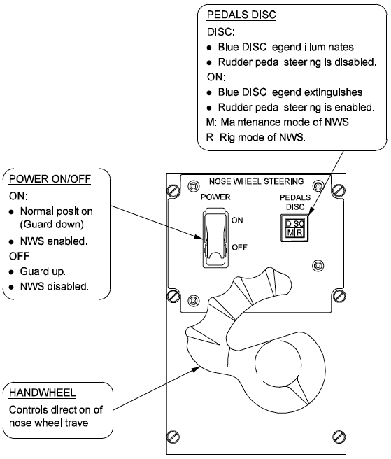
[G450 MM, § 32-50-00 ¶] Nose wheel steering is selected with the guarded POWER switch forward of the handwheel on the pilot side console. Rudder pedal steering is selected with the PEDALS DISC switch to the right of the POWER switch. The POWER switch must be selected ON for the rudder pedal switch to operate. The light in the rudder pedal switch does not come on in the normal on position, but a blue OFF legend within the switch will alert the crew if the system is selected off. Below the OFF legend are two internal maintenance indicators for use in performing system checks and aligning the rigging between the RVDT and potentiometer in the tiller assembly and on the steering gearbox. The PEDALS DISC switch contains three internal lights: DISC, M (maintenance) and R (rigging)
Back in the GIII there was no rudder pedal steering and Gulfstream put in this rudder pedal disconnect switch to placate the old heads who thought rudder pedal steering was an element of witchcraft. A misunderstanding of this switch has resulted in one mishap, the Palwaukee GIV incident. My advice: leave the pedals connected. The nosewheel remains centered for one second after it becomes compressed, it isn't going to be a problem.
Operation
[G450 AOM, § 2A-32-50 ¶1.A.] A RVDT is mounted on the gearbox and sends a feedback signal to the ECU. The ECU compares the moderated command signal from the cockpit tiller handle RVDT to the actual nosewheel position as reported by the gearbox. When the nosewheel corresponds to the commanded position, the ECU signals the EHSV to neutralize steering pressures to the hydraulic motor. When not in active steering mode, the tiller control handle is returned to the neutral, or straight ahead position by a centering spring and cam when the handle is released. If the system is selected off, the nose wheel is free to turn in a passive mode, responding to the tracking forces of differential braking or engine power settings. The trapped hydraulic fluid in the system will also act as a shimmy damper when the system is not powered.
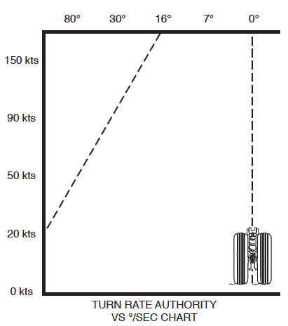
[G450 AOM, § 2A-32-50 ¶1.A.] Steering the nose wheel with rudder pedal commands is functionally identical to operation of the tiller handle. A RVDT is located on a connector rod beneath the cockpit floor on the copilot side. Displacement of the rudder pedals left or right prompts the RVDT to signal the steering command to the ECU. The ECU limits the rudder steering command such that full pedal deflection will result in a maximum nose wheel displacement of seven degrees (7°) left or right. If the tiller control handle is displaced from neutral, the ECU will algebraically sum the tiller and rudder pedal commands up to the maximum nose wheel displacement of 80°. If the tiller handle RVDT malfunctions, the nose wheel steering authority of the rudder pedals is increased to 16° left and right below 20 kts, with the authority linearly decreased to 10° at 60 kts and limited to the normal 7° at 90 kts and above.
[G450 AOM, § 2A-32-50 ¶1.A.] To ensure that the nose wheel remains centered prior to nose wheel retraction into the nose wheel well, internal centering cams are incorporated in the shock strut, and the steering system is restricted to ground operation only by several safeguards. The landing gear lever handle must be in the down position to complete the electrical circuits for steering. Hydraulic pressure for steering is provided through the left hydraulic system lines. The hydraulic pressure must pass through two solenoid controlled shutoff valves (SOVs) before reaching the EHSV and steering actuator.
[G450 AOM, § 2A-32-50 ¶1.A.] When the nose gear WOW switch is compressed, the ECM initiates a one second delay before responding to steering commands from the rudder pedals or the control wheel, maintaining the nose wheel in the centered or straight ahead direction. The delay avoids abrupt steering commands caused by large rudder pedal inputs during crosswind landings.
Turn Authority
[G450 AOM, § 2A-32-50 ¶1.A.] The nose wheel steering is controlled electrically and operated hydraulically and mechanically. The steer-by-wire system uses inputs from a tiller handle mounted on the pilot side console or signals from rudder pedal position. The nose wheel may be turned 80° (± 1.6°) left or right of center with the cockpit control tiller, or 7° (±1°) using only rudder pedal input. Control tiller and rudder pedal inputs are additive, but total nose wheel displacement is limited to 80° (±1.6°).
The tiller handle is mechanically connected to system control elements mounted underneath the handle within the side console. When the system is selected on, moving the control tiller turns a shaft connected to a Rotary Variable Displacement Transducer (RVDT). The RVDT provides an electrical signal of the direction and amount of displacement of the tiller handle from the centered position. The electrical signal is received by a microprocessor called the Electronic Control Module (ECM). The ECM modulates the turn command signal by compensating the turn command for groundspeed. The ECM receives groundspeed velocities from micro Inertial Reference Units (IRUs) #1 and #2 and reduces the amount of nose wheel displacement from center with increased speed. The reduction is inverse to groundspeed in both turn rate and control tiller authority. At 182 kts, turn rate is limited to 8° per second, and increased linearly to a turn rate of 22° per second at 20 kts or less. Control authority is limited to 24.5° left or right at or above 90 kts, and expanded to the full limit of 80° below twenty knots (20 kts).
Towing
[G450 AOM, § 2A-32-50 ¶1.A.] The nose wheel steering linkage must be disconnected for aircraft towing by removing the connecting pin on the torque link between the actuator and the nose wheel. A tow bar is then connected to the nose wheel axle. Care should be taken to ensure that the nose wheel is not pivoted in excess of the 80° limit. Exceeding the displacement limit will damage the internal mechanical stops. A pop-up indicator is installed on the forward section of the top of the steering unit to warn of an overtravel condition. If the indicator is visible during preflight inspection, the nose wheel steering collar should be removed and inspected for damage.
Tires
I've moved everything I know about tires to here: Aircraft Tires. There is a lot of Gulfstream specific information.
Wheels and Brakes
The G450's brakes are very good but they are different than the GIV and GV. Operationally they work well, but when things don't go well there are a few differences you should be aware of. The G450 anti-skid system, for example, does not use IRS or GPS speed inputs. All speed information comes from the internal wheel speed sensors. The brakes can receive hydraulic pressure from the left hydraulic system, even if powered by the PTU. It can also receive pressure from the aux hydraulic pump, but you need to make sure the flaps are not moving because they will outdraw the brakes. The emergency/parking brake can be modulated at the handle, but the pressure is applied across all four main gear.
Operational Summary
[G450 MM, §32-40-00 ¶4.A.] The landing gear incorporates dual wheels on each main and nose landing gear strut. The nose wheels are free to rotate, with no braking system installed. The main wheels are fitted with a hydromechanical analog braking system with the cockpit brake pedals mechanically connected to valves. The valves apply hydraulic pressure to the brakes in response to brake pedal displacement.
The braking system incorporates an electronic subsystem offering full anti-skid protection with additional features to prevent any brake pressure application to the wheels prior to touchdown or locked wheels during landing rollout. The brake system uses pressure from the left hydraulic system. The power transfer unit or auxiliary pump can pressurize the left system fluid to provide braking if any failures occur with the left system. If left system pressure or fluid is not available due to a combination of malfunctions, the braking system is supplemented with an independent parking / emergency brake system using stored accumulator pressure for manually modulated brake application without anti-skid protection.
A brake temperature monitoring system provides a temperature display of each of the four brake assemblies in the main wheels. An amber crew alerting system Brake Overheat message is provided if one or more brake assemblies exceed 650°C. A peak temperature display is also provided to assist in the determination of the brake cool-down time required prior to the next takeoff.
Pedals to Metering Valves to Shuttle Valves
[G450 AOM, §2A-32-40 ¶5.] The brake system applies up to 3000 psi hydraulic pressure from the left hydraulic system to the main landing gear brakes in response to cockpit brake pedal commands. The left and right pilot and copilot brake pedals are mechanically linked to the left and right brake metering valves in the nose wheel well. The metering valves open in response to brake pedal deflection, porting increased pressure with greater brake pedal application. The left and right brake metering valves are plumbed to both the left and AUX hydraulic systems. Immediately downstream of the metering valves in the nose wheel well are two shuttle valves (one for each metering valve) that shift between either left or AUX system pressure.
[G450 AOM, §2A-32-40 ¶5.] If left system pressure drops below 1500 psi during braking, internal stops in the metering valves shift, allowing AUX system pressure though the metering valves to operate the brakes with a slight increase in pedal effort required. The AUX hydraulic pump will pressurize automatically (if armed) with the loss of left system pressure below 1,500 psi and subsequent deflection of the brake (rudder) pedals 10° or more, closing limit switches. The limit switches in combination with the left system low pressure switch complete the circuit to power the AUX pump.
The metering and shuttle valves operate on a simple principle: force wins. The pilot who presses a brake pedal harder controls that brake, ensured by two metering valves, one for the left and the other for the right brakes. The shuttle valves move to permit the higher pressure from either the left or aux hydraulic system to flow downstream to the anti-skid control valves.
Wheel Speed Sensors
[G450 AOM, §2A-32-40 ¶6.] Hydraulic pressure is metered by the anti-skid control valves in response to commands from the Digital Anti-skid Control Unit (DACU). The DACU, located in the baggage compartment electronic equipment rack, monitors wheel speeds using data supplied by transducers mounted on the wheel axles that are spun by the rotation of the wheel. The transducers act as generators, producing an alternating current (AC) signal at a frequency proportional to wheel revolution rate.
When wheel speed is greater than 47 knots, the DACU also provides a wheel speed monitor signal to MAU #1 and #2 for communication to applicable circuits of the ground spoilers and thrust reversers for secondary control signals in the event of WOW system failures.
There are four wheel speed transducers, one per main wheel, which report wheel speed to the Digital Anti-skid Control Unit. This is the only source of wheel speed used in the G450 to modulate braking and provide wheel spin up information for ground spoilers and thrust reversers. This information is contradicted several places in the G450 AMM, G450 AOM, and various FSI training publications. Why the confusion? The GV and G550 use a combination of wheel speed sensors and IRU speed.
Anti-Skid Control Valves
[G450 AOM, §2A-32-40 ¶5.] From the shuttle valves, brake command pressure is routed to the anti-skid control valves. The anti-skid control valves electronically regulate hydraulic pressure to the brake assemblies to maintain wheel rotation during braking.
Hydraulic fuses detect a broken or damaged hydraulic line as indicated by increased fluid flow and close to prevent system fluid loss. Pressure transmitters installed in the brake lines electronically provide readings to the MAUs. The left brakes are monitored by MAU #1, the right brakes by MAU #2. The MAUs communicate applied pressures to the MWS for display on the Brakes system page. In normal operations, left system pressure operates the aircraft brakes.
The anti-skid control valves use electronic signals from the DACU to decide when to decrease applied brake pressure. (More on this a little later.) The electrons can be bypassed by turning the anti-skid off or by using the parking/emergency brake.
Brake Assemblies
The brakes, wheels, anti-skid, and brake temperature monitoring sensors were provided by a ABSC, Aircraft Braking System Corporation, in Akron, OH, a trade name of Meggitt Aircraft Braking Systems.
Figure: Main Landing Gear Brake Assembly, (G450 MM, §32-43-00, Figure 1)
[G450 AOM, §2A-32-40 ¶4.] Brakes have three rotating discs (rotors), two stationary discs (stators), an end plate and a pressure plate. All of these elements are of carbon-metallic alloy, and are referred to as a whole as the disc stack or heat pack. The stators are attached to a torque tube that in turn is bolted to the aircraft landing gear assembly. The rotors engage the wheel, with notches in the rotors fitting keys on the interior of the wheel hub. The wheel turns on the wheel bearing, with the rotors spinning between the brake stators. Brake piston retraction springs maintain sufficient clearance between the rotors and the stators to permit the wheels to turn freely. Five hydraulic actuating pistons are built in the brake housing. When the brakes are activated, hydraulic pressure is increased within the pistons, moving them outward from the housing compressing the pressure plate, and reducing the clearance between the rotors and stators. The surfaces of the rotors and stators are pressed against each other, producing friction that slows the rotating wheel.
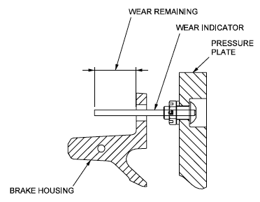
Figure: Brake Wear Indicators, (G450 MM, §32-43-01, Figure 601, Detail A)
[G450 AOM, §2A-32-40 ¶4.] A brake wear indicator is installed on each wheel. The indicator is a pin that extends from the pressure plate through the housing, protruding from the brake assembly. The amount of pin protrusion is indicative of the combined thickness of the rotor and stator discs. Parking brake pressure is applied to accurately read wear pin length.
[G450 MM, §32-43-01 Para;1.B.(1)(i)] If end of brake wear indicator on any brake assembly is flush with or below brake housing, replace brake assembly.
Unlike some older Gulfstreams, there is no option for installing spacers to get more life out of a set of brakes.
[G450 AOM, §2A-32-40 ¶4.] Main wheel brakes are equipped with temperature monitoring and digital anti-skid protection. The Digital Anti-skid Control Unit (DACU) automatically applies hydraulic pressure to stop wheel spin as the landing gear are retracted into the wheel well.
Parking / Emergency Brake Accumulator
Figure: Parking / Emergency Brake, (G450 MM, §32-48-00, Figure 1, Detail A)
[G450 MM, §32-48-00 ¶3.A.] The parking / emergency selector valve is operated by the parking / emergency brake control handle and cable assembly. The valve is normally closed to retain pressurized fluid in the accumulator and dump brake pressure to return. When the valve is activated, the initial travel offers proportional pressure to the brakes. When the valve is fully opened, full accumulator or auxiliary system pressure is applied to the brakes.
[G450 MM, §32-48-00 ¶3.C.] The parking / emergency brake hydraulic accumulator provides an emergency source of hydraulic pressure to the brakes. In addition to emergency stopping capability, the accumulator also supplies pressure for aircraft parking. Accumulator pressure is maintained when auxiliary hydraulic pump is switched off by a 1200 psi (precharge pressure) nitrogen bottle located in the nose wheel well.
[G450 AOM, §2A-32-40 ¶5.] The accumulator, when fully charged, contains sufficient pressurized hydraulic fluid for at least six brake applications. The PARK / EMER BRAKE handle on the cockpit center console is connected by cable to a modulating valve that ports the accumulator fluid directly to the wheel brakes. Emergency brake pressure is applied simultaneously to all four wheel brakes - some modulation can be accomplished by pulling out the handle between ¼ and ½ inch. Handle travel beyond approximately ½ inch results in the application of full accumulator pressure. No anti-skid is available with emergency braking.
[G450 AOM, §2A-32-40 ¶5.] To apply accumulator pressure for parking the aircraft, the PARK / EMER BRAKE handle is pulled up and then rotated clockwise, latching the handle in the applied position. To release the PARK / EMER BRAKE, pull the handle up and rotate counterclockwise allowing the handle to retract to the stowed position. Parking / emergency brake operation is monitored by a pressure switch downstream of the accumulator valve.
The "at least" six brake applications depends on how smooth you are with the handle. You should try to pull less than you think you need and see what happens. Then apply a little more. Applying too much and then backing off wastes accumulator pressure.
Anti-Rotation for Gear Retraction
[G450 AOM, §2A-32-40 ¶5.] An anti-rotation feature is incorporated in the braking system to stop main wheel spin prior to gear retraction into the main wheel wells. When the landing gear control handle is selected to the retract position, gear up pressure sends a signal to the Digital Anti-skid Control Unit (DACU) to operate the brake metering valves, reducing wheel spin through brake pressure modulation. Reduced braking is applied for 10 seconds to decelerate wheel rotation at a rate of 100 ft/sec2. A zero wheel speed is reached within five seconds or an amber CAS caution message of “Wheel Despin Fail” is displayed.
Anti-Skid Brake Protection
[G450 AOM, §2A-32-40 ¶6.] Anti-skid protection for the main landing gear brakes operates by regulating hydraulic pressure applied to the brakes to maintain wheel rotation. Anti-skid is effective from 200 knots down to 10 kts. (Below 10 knots, the main wheel brakes may be locked by brake pedal commands in order to turn the aircraft within a minimum radius.)
Digital Anti-Skid Control Unit (DACU)
[G450 AOM, §2A-32-40 ¶6.A.] The DACU is a digital electronic component that receives multiple inputs from aircraft systems to determine the effectiveness of wheel braking. Information is derived from:
Landing gear control handle position
Left and right main gear weight-on-wheels (WOW) switches
Wheel rotation speeds from each inboard and outboard wheel on both main gear struts
Brake temperature probes
The DACU has two circuit boards for monitoring wheel speeds and controlling brake application: one board is dedicated to the inboard wheels on each strut, the other to the outboard wheels on each strut. Each board is separately powered by the essential DC busses with a dedicated circuit breaker in order to provide system redundancy. Failure of one board will not effect symmetric anti-skid protection by the remaining board. The board for the outboard wheels is powered by the left essential bus, the inboard wheel circuit board is powered by the right essential bus.
The DACU compares the speed (frequency of the AC signals produced by the rotation) of the wheels to a reference value. The reference value is either a deceleration rate of 25 fpm/sec2, or a deceleration rate trend of the previous 3 seconds. When the DACU detects a rotational speed rate decrease greater than the reference value, it signals the anti-skid control valve for that wheel to reduce hydraulic pressure to the brake to eliminate the wheel skid. The amount of hydraulic pressure reduction is proportional to the actual deceleration rate difference from the referenced value. Anti-skid protection endeavors to keep wheel rotation velocity just above the skid point.
Problem one: The person who wrote this AOM paragraph could not have been an engineer because 25 fpm/sec2 is not a valid value of deceleration. Assuming they meant 25 fpm/sec that equates to losing 14 knots every second, a pretty aggressive stop. That would make sense as a reference value to consider releasing brake pressure.
Problem two: Using a three second trend of actual braking is nuts, since if you started a gentle deceleration and figured out you need more, you don't want the anti-skid overruling you at this point.
Anti-Skid Control Valves
[G450 AOM, §2A-32-40 ¶6.B.] Hydraulic pressure to each wheel brake is modulated by an anti-skid control valve. The valves reduce the hydraulic pressure commanded by the rudder pedal brakes to prevent tire damage and preserve aircraft directional control during braking. Each inboard or outboard valve is electrically connected to the respective circuit board in the DACU for valve modulation commands.
Touchdown Protection
[G450 AOM, §2A-32-40 ¶6.C.] Touchdown protection prevents hydraulic pressure from reaching a wheel brake until the aircraft is established on the ground and the wheel has begun to rotate and achieve a speed sufficient to confirm that a malfunction has not occurred that prevents the wheel from turning freely. Touchdown protection is initiated when the landing gear control handle is selected to the extend position. The anti-skid DACU determines the aircraft air/ground status from a combination of the position of the WOW switches and ARINC 429 data. The DACU also monitors wheel rotation speed to ensure that wheel speed is less than 30 knots. When DACU determines that the aircraft configuration indicates that a landing is in progress, the control unit establishes the touchdown protection mode. The mode opens the anti-skid control valves, dumping hydraulic pressure to a wheel brake until the wheel spins up to a velocity of 30 knots. This protection mode prevents landing with brake pressure inadvertently applied to the wheel brakes.
Locked Wheel Protection
[G450 AOM, §2A-32-40 ¶6.C.] Once the aircraft is established on the ground in a normal braking condition, a similar protection acts as a backup to normal anti-skid protection to avoid locked wheels on the ground during roll out. If a rotational speed difference of approximately seventy percent (70%), as measured between inboard wheels or between outboard wheels is detected, hydraulic pressure is removed from the slow wheel brake until wheel rotation recovers to match the speed of the corresponding wheel on the opposite landing gear.
Hydroplaning Protection
[G450 AOM, §2A-32-40 ¶6.C.] If a locked wheel condition persists for more than 5 seconds, pilot applied pressure is returned to that wheel (the wheel is assumed to be deliberately locked). This feature is useful in circumstances of severe hydroplaning or icing conditions where wheel rotation is minimal or nonexistent. Removing all hydraulic brake pressure to the locked or non-rotating wheel prevents damage / blow outs when the aircraft exits conditions of very low friction (standing water or ice patches) during rollout.
So how does the anti-skid system really work? It is hard to say because the AMM and AOM are littered with cut and paste errors when assuming things work like they do in the GIV, GV, and G550. Filtering out the obvious mistakes, I have concluded the following is correct:
Touchdown Protection. The DACU determines a landing is in progress from the gear handle and WOW switches. The DACU then dumps brake pressure until the wheels achieve 30 knots.
Reference Speed. The DACU's compare each wheel's speed against a reference speed. If a wheel decelerates more than 14 knots per second, pressure to that wheel is released.
Locked Wheels. If an inboard wheel's speed differs by more than 70% from the other inboard wheel, hydraulic pressure is released from the slower wheel until its speed recovers. The same process occurs for the outboard wheels.
Brake Temperature Monitoring
[G450 AOM, §2A-32-40 ¶7.] Brake temperatures of each wheel are monitored to report brake temperature, warn the crew of brake overheat and as an indication of a malfunction such as a dragging brake. A thermocouple to monitor temperature is installed on each brake with temperature communicated to the DACU. The DACU forwards temperature data to the MAUs #1 and #2 that in turn provide the information to the MWS that formats temperature information for display on the Brakes system 1/6 window display. The MWS also stores a reading of the highest brake temperature indication during each flight cycle for display on the Brakes system page for use by the flight crew in determining brake cooling time requirements. The MWS will delete the highest previously recorded reading and record a new peak temperature whenever aircraft groundspeed exceeds 60 knots or when the landing gear is selected to the extend position. The sixty (60) knot groundspeed parameter is to enable recording the highest brake temperature during an aborted takeoff.
[G450 AOM, §2A-32-40 ¶8.B.] The highest brake temperature recorded during the current flight cycle is shown below the temperature bar graphs. The data includes the identification of the brake (e.g. “LO” = left outboard), the highest temperature for that brake and the time that the high temperature was recorded in universal standard time (GMT).
[G450 Cold Weather Operations Manual, Pg. 16] Taxi: Use brakes to build up brake temps to a minimum temperature of 100°C. This aids in dissipating any moisture in the brakes.
[G450 AFM, §3-18-50] Landing gear should remain extended until all brake temperatures are below 200° C. Verify Brake Overheat message is extinguished.
Brake Synoptics
[G450 AOM, §2A-32-40 ¶8.B.] If the anti-skid system is turned off, an expanded brake applied pressure scale is available. The expanded scale is shown as an aid to the flight crew in monitoring the precise amount of hydraulic pressure commanded with brake (rudder) pedal depression. The expanded scale has a resolution of 40 psi and is depicted whenever applied brake pressure for all brakes is less than 800 psi. If more aggressive braking is commanded, the scale will revert to the normal range (0 - 3,000 psi) when applied brake pressure exceeds eight hundred (800) psi.
Below the text line is a bar graph display of brake temperatures. The format is identical with the applied brake pressure graphics except that the central scale is calibrated in degrees centigrade (°C) and has an expandable range of 0 - 999°C with a one degree (1°C) resolution. Each bar graph is depicted in green at temperatures below 625°C - when a brake temperature exceeds that threshold, the bar graph will be shown in amber, and will remain amber colored until the associated brake cools to 600°C or less.
[G450 AOM, §2B-09-00, page 22] The lower half of the brakes synoptic page displays the BTMS readouts. The display consists of four bar graphs for left and right inboard and outboard brake temperatures, corresponding digital readouts, and a thermometer scale. The label TEMP is centered at the top of the BTMS thermometer. The thermometer scale has a range of 0° to 999°C with a resolution of 1°C and values labeled every 100°C up to 650°C. Above 650°C, the thermometer scale displays slanted amber lines up to the maximum displayable value. Brake temperature readouts from the four brake temperature sensors are displayed left to right. A bar graph and a digital readout are displayed for the temperature for each brake. Bar graphs and digital readouts have a displayable range of 0° to 999°C with a resolution of 1°C. When brake temperatures exceed 650°C, the bar graph and the digital readout for the individual brake turns amber. The bar graph and digital readout return to white when the brake temperature decreases to 600°C. The bar graph and corresponding digital readout are replaced with a red X when it is invalid.
If the MWS (or FWC in older airplanes) gets an invalid signal, loses the date, or has some other issue it could dump the most recent highest recorded temperature. If this happens, you will dashes or an X instead of the recorded temperature and wheel position. If this happens, the system is no longer computing your brake energy limits and it falls upon you. If you know your brakes are cool all you have to do is disable the BTMS function of the performance computer
See G450 Takeoff Data Initialization.
The system will reset itself the next time you go faster than 60 knots. If this isn't your first takeoff of the day and you aren't sure how much energy you have left in the brakes, you need to figure that out before your next takeoff to insure you have abort capability. Here's how to do that:
Limitations
[G450 AOM, §2A-32-40 ¶9.] Takeoff is permitted with Anti-Skid system inoperative, provided the runway is dry, Ground Spoilers are operative, 20° flaps are used, and the Cowl and Wing Anti-Icing systems are not used. Dispatch with reference to the MMEL.
References:
Gulfstream Cold Weather Operations Manual, Applicable to All Gulfstream Large Cabin Airplanes, Includes G650, G550, GV, G450, GIV, G1159 Series, and G159 Series, Basic Issue, October 30, 2012
Gulfstream G450 Airplane Flight Manual, Revision 35, April 18, 2013
Gulfstream G450 Maintenance Manual, Revision 18, Dec 12, 2013
Gulfstream G450 Operating Manual Supplement, G-450-OMS-02, Extended Operations (ETOPS) Guide, Revision 2, April 2, 2009
Gulfstream G450 Performance Handbook, GAC-AC-G450-OPS-0003, Revision 20, November 30, 2011
Gulfstream G450 Quick Reference Handbook, GAC-AC-G450-OPS-0003, Revision 34, 18 April 2013
Gulfstream G450 Weight and Balance Manual, Revision 3, March 2008
Salamankas, John, Brakes 101.
Salamankas, John, Tire Wear.


